DIY PAR meter

Pretty much, coupled with tuned sensitivity on the substrate its self.

To the person building it, which part number diode did you use? Whats your amplification strategy?

I have an Apogee sensor here (not with the overpriced multimeter though), so we can do some comparison readings. I have some MH, LED and T5s amongst various setups.

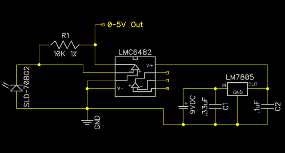
The "overpriced" multimer has filtering and amplification circuits that correct the sensor readings and fit them to the PAR curve. That is, the op-amps transfer functions are tuned to profile of the sensor and its physical filters and designed to correct the non-linearities and weight the response according to the proper curve and the defects in the sensor and filter/optics. In theory it is a very simple device, in practice building it so that the results are accurate and meaningful is no as easy.

I have a lot of experience with tri-color devices (used for display calibration) and even though many use the SAME sensor, the supporting hardware (filters, amplificiation and/or software correct) make the difference between a useless toy and a precision instrument.

Also consider, that many of the sensor manufacturers will tweak the specs of the sensor based on the needs of an OEM :)
 
Bean, I completely agree with you on the non linearity part. Its going to need some tweaking and lab testing.

The newer apogee sq110/120 deliver a compensated signal direct from the sensor; they sell it for use with external data recorders. In fact their handheld now has the sensor stuck inside of it (which lets them change calibration with code) .
 
I am using the sq110 in my lighting controller... It is gathering dust on a shelf waiting for a motivated rainy day (along with 1000 other dusty project components waiting for their rainy days).
 
Parts came in last night.. Got the sensor soldered to the wires and installed in the housing and all sealed up so its waterproof.. Got to complete the external circuitry (amplifier/9Vto5V convertor,etc.. tonight, should have the unit completed by tomorrow ready for testing.. I want to set up initial calibration/output based on the noon sun to be midway in the output. So far so good. Sensor output seemed really linear and the teflon diffuser seemed to be the perfect thickness (1mm).
I'll finish the unit and dunk it in the tank and take some measurements to see if its actually giving a reasonable output.

Still looking to see if anyone will let me borrow their PAR meter to compare readings.. I think the LFS has one that they will let me borrow but if anyone else wants to offer that would be great too. IT should only take me a day to compare readings and be able to scale the sensors output to PAR readings.
 
Sensor is finished/working as designed... (need a trip to radio shack for an enclosure for the battery and circuit board but thats just the frills to make it look pretty)
Need to get out in the sun tomorrow at noon (yeah for the weekend) for baseline calibration. Found a great site from Apogee that lets me calibrate the sensor (close enough for now) based on the noon sun in my area. http://clearskycalculator.com/

I will then be able to take some test measurements in my tank to see where I'm at.. Overall I'm very happy with this first go at it. I will post information (schematic/parts list,etc..) in a few days or so when its finalized. Still need to figure out a good way that anyone can create the housing/diffuser (I'm lucky and have full access to a machine shop so mine is a little over typical DIY right now).

But the response/linearity of this sensor I used is GREAT.. Seems VERY accurate to even the slightest changes in light levels. Even a .005" change in height from the light source registers a change in readings. (slid some shim stock under the sensor)

Found a local guy with a PAR meter that is willing to let me compare my readings to the Apogee unit too.
 
Cool... let is know how it goes. It would be wonderful to find out that a stock sensor is as linear as some of the products used in OEM units like the Apogee.
 
pics.gif
 
Cool... let is know how it goes. It would be wonderful to find out that a stock sensor is as linear as some of the products used in OEM units like the Apogee.

This is crazy, you finally got bean onboard and we still have no pictures or updates.:frog:
 
Sorry..been really busy.. Playing with my new toy
Should get back to it this weekend.
Assuming the wife doesn't give me a big "honey do" list
 

Attachments

  • Tundra1.jpg
    Tundra1.jpg
    42.9 KB · Views: 15
that is the ugliest truck I have ever seen :strange:
a DIY par meter is way more important then a ford!
UPDATES!!!!!
 
Ur truck is awsome but PAR meters are better. There is a Tundra like that that rolls around where I live. Wish I had never gotten rid of my Tacoma.
 
OK.. I've been REALLY lazy the past few weeks.
and yes its a Toyota Tundra 5.7L V8 371HP, 400+ft-lbs of torque.. It's a beast..

I have completed the par meter but just don't have access yet to a real par meter to verify if its producing any decent numbers. But it does sweep from 0 to 5V when subjected to varying light levels. Full noon sun gives about 4.5V.
I will post the schematic and parts list this weekend. (unless I get lazy again)
Hopefully my guy will come through with letting me borrow his par meter.. If not I will just pack it up and maybe send it to one of the guys on here that has one.
 
how much has it COST so far to build one...and, simply put, would you say that it's something that any fool (like me) can build if we just folowed your instructions...?

this is really cool.
 
To do what Bean suggested you should be able to adjust the gain and the offset for the O.A. The schematic presented needs to be updated a bit. I doubt you will be able to match readings from a PAR meter unless you connect this to an Arduino analog pin and have an equation ahead.

cheers,
MaLi

PS. For those with diy Arduino controllers this can be a nice way to monitor the bulb's intensity drift (not spectrum drift).
 
Back
Top