Has anyone made an LED driver based on LM3463 6 channel driver IC?

tomservo

New member
I'm wondering if anyone has experience with this chip, it's a 48L WQFN package, which is my biggest concern. It's a 6 channel driver with 4 PWM / analog / serial dimming inputs.It even has built in thermal foldback dimming.

Anyways, I am in a situation where I need to make drivers for 5 or 6 "dream chip" type multichannel emitters. I tried LDD drivers on the last couple that I made, and out of the 12 LDDs I was able to order, 3 were bad! Plus, they don't support analog dimming, and they are kind of pricey when you need 40 or 50.
 
I took a look at the specs and it's definitely an interesting find as it's input can handle up to 95V. The downside is it's output current- only 200ma. That's way below the current level that each channel of the "Dream Chip" can handle.
Are you still looking for a driver capable of 1400ma per channel? I'm pretty sure that your options are still limited to a DIY driver based on the National Semi-conductor LM3409 buck controller IC. The LM3409HV can accept both analog an PWM signals directly, and handle up to a 75V input /5000ma output. There's a wealth of information about it here on the "DIY LED Driver" thread, if that's the route you end up taking.
 
No, that current rating is for driving the output mosfets, you can select your mosfets and current sense resistors to drive any load you would like. You could even use the LM3466 load balancer chips to use one driver to run many strings.

Yep, I'm still looking for 1400ma drivers. The LM3409 looks easy enough but the efficiency is a bit lame.
 
Mosfets- How did I miss that? I saw them in the example schematic, but clearly forgot that they were there. That's the part I hate about spec sheets, they tend to only describe the component's capabilities- not what it's truly capable of when paired with other components. Why don't the chip manufacturers just plainly say - "Hey look at what OUR chip can do! Pair our chip with this... this... and that... and you can do this!" Wouldn't that approach make selling them easier?
I found a few suppliers that have an LM3463 EVAL BOARD in stock, but they're upwards of $150 a pop! That's a lot coin to drop- just to "Evaluate" it. LOL
I'll be interested to see where you go with this, as this "Dream Chip" driver would be a compact solution for multi-channel Led's.
 
The plan is to print the datasheet and do some math to figure out the components I need, to get started. I will need to figure out how to choose mosfets, any advice you might have there is appreciated.

I want to design the board with dip switches or jumpers so that 0-10v or PWM control can be selectable, and the plan is to make the boards so that all 6 channels are usable. 5 channels with go to one on board plug, and the 6th will be wired to an additional plug.

I have a connection here to a place that does pick-and-place / board prototyping on their spare machine time, so I may look into having 10 boards made.
 
Newark sells a bunch of great led driver chips. You need to reflow solder most of them, but you can potentially get all the parts in through-hole configuration and solder the SMD packages to converters.
The LM3421 especially caught my eye. 1000ma max output, and has the parts list in the datasheet.
 
I've completed a good bit of the math for the LM3463 board I will be making. These do need to be reflowed, but I have sufficient equipment for the job. I even have some low temp solder paste somewhere or other.

The thing about this chip is, by changing only the current sense resistor, you can select the max current you want. It also has provision for an analog dimming (of all channels) that functions as a max current trim, so you could configure the board for 3A, and then dial it back to 1.5A and the PWM/voltage dimming would be 0-1.5A. I selected a mosfet that will be good to 3A no problem, even without any cooling area for the mosfets. Probably will be fine to 4.5A even, and that is per channel. I think I can definitely get this onto a 5x10cm board, maybe even a 5x5 if I put mosfets on both sides. All the connectors are going to take up a considerable amount of real estate.

o2surplus: I want to use the power supply voltage trim, but the LM chip outputs 0-2.5v and the power supply wants 0-5v (0-6v actually but 0-5 is 0-100%). This will help system efficiency a good bit, but do you know how I can convert the signal?
 
o2surplus: I want to use the power supply voltage trim, but the LM chip outputs 0-2.5v and the power supply wants 0-5v (0-6v actually but 0-5 is 0-100%). This will help system efficiency a good bit, but do you know how I can convert the signal?

I'm not sure if I'm following you? Are you saying that you need to figure out a way for a 0 - 2.5V signal to control a larger 0 - 5V signal? Sounds to me like it's a job for some type of comparator circuit. Let me know if I'm correct in my assumption?
 
What I need is to use a 0-2.5v signal to drive a 0-5v input, and I'm not sure how this is done. I have +5v 200ma available on the board, as well as a 6.7v 10ma source from the LM chip, but for signal purposes this may be sufficient.
 
What I need is to use a 0-2.5v signal to drive a 0-5v input, and I'm not sure how this is done. I have +5v 200ma available on the board, as well as a 6.7v 10ma source from the LM chip, but for signal purposes this may be sufficient.

You use an OP-amp to make a voltage doubler. google the circuit.
 
So the "output" is actually a current sink.. From what I can tell, it is designed to sink the voltage to zero to achieve the highest voltage, and for lowest voltage, it is 3.1v.

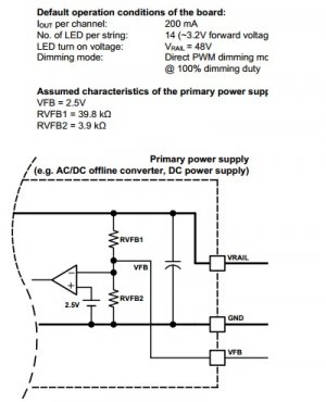
Here is a circuit diagram from the evaulation board - not shown is the 1.2v drop diode and 2.94kohm resistor on the board itself. Which work out to 1ma current and 3.1v - the line is "fed" 4.28v from the voltage divider R1 and R2, and then the result is fed into an op amp. I think their design is for the op amp to control the 2.5v feedback into the power supply's regulator.

Is what I need, then, to simply change the op amp into an inverting op amp, setup to convert 3.1-.1v to 2-5v?


Edit: I just thought of using the circuit as it was intended, to bias a voltage regulator - I am thinking of putting in some cheap 5v regulator and with the aid of a diode or two to drop the 4.28v to .8v. Thoughts?

Edit again: I have found Rohm BD00HA3WEFJ 1.5-7v regulator, uses .8v reference voltage. Should be as simple as adding a voltage divider between the "FB" junction and the feedback on this regulator, to output 1.5-4.8v, which is good enough for my purposes.
 

Attachments

  • power supply feedback.jpg
    power supply feedback.jpg
    52 KB · Views: 2
Last edited:
A major design concern with LEDs is heat. If you use mosfets with one voltage
source and 4 channels. You take one channel and dim it. It has to reduce the
power to the LED. It can either pulse it or the mosfet acts as a variable resistor.

1. Pulse issue.
"facilitate average LED current control by means of PWM dimming. "
This is a different type of dimming than used on many LED controllers.
The LED is being pulsed at a varying duty cycle. Instead of the current being
reduce by a voltage or pwm signal. Not sure if an issue with corals.
The dimming frequency is mentioned as an example was 488hz for 8 bit.

2. Heat issue v=ir p=iv
This chip has a different modes that it would take a while to review if you use analog
you could have heat issues with the sense resistor and mosfet.

What power supply do you plan on using. There can be quite an efficiency loss.
Your power supply cost may be more than you save.

Your mosfet also needs to have a low rSD on
The one TI uses is.
rDS(ON)= 45mΩ
 
I am going to use a meanwell RS-1000 @ 91% efficiency.

I think the 488Hz has to do with matching up with 256 bit resolution, and doesn't necessarily reflect the PWM frequency applied to the mosfets.. Since on the evaluation module user guide, there is a chart showing 3v-2v dimming and the pulse on-off cycles are 1ms each. IE @3v there is an approx .5ms on and .5ms off (~50% duty). It may be that using direct PWM dimming, it's possibly to get flashing but I am thinking probably not. It would be useless in lighting applications if it was like that, after all.

It's not about savings in this case; I tried using LDD drivers and 3 out of 12 were bad, plus they don't have anything over 1000ma. I need to make 25 channels worth of drivers; I am not seeing many worthwhile options out there. Using individual power supplies is out of the question, I'd need a capacitor bank just to start that many, and a 200 amp service!
 
OK, so after a careful review, I am thinking about switching my design (now that the circuit diagram is complete, DOH) to the Monolithic Power MP2483. It's an integrated 2.5A LED driver that does 5v PWM and .7-1.4v analog dimming. The .7-1.4v is a bit annoying but I think I can live with it, and there is probably some kind of op amp circuit to compensate, but I don't think I'll bother. With a voltage divider it works out to 5-10v 0-100% dimming, that is good enough for me.

They're only $2.08 in qty 25 from mouser. The external components are a handful of resistors, some small capacitors and one 4.7uH choke. $.25 each so I expect the per channel cost to be somewhere around $2.50-2.75, not bad at all!

Edit: I just found an impressive product from ISSI - this one is meant to run on rectified 85-265VAC - no AC-DC power supply required! http://www.mouser.com/ds/2/198/31LT3918-10728.pdf
 
Last edited:
Rick, I tried the ISSI unit, and couldn't get it to work sensibly, and I gave up when I blew one of the mosfets.. I should have ordered a spare or something. That said, I have the parts to try on the MP2483 chip, when I get a chance. We just bought a house so right now it's not a big priority compared to packing. Once the packing is done I will put together a circuit and try to come up with a +48v source. I may have two 24v power supplies I can tie together for that.
 
I'm subscribed to your thread, so I'll be watching Tom. I would think more guys or manufactures would have a interest in a supply driver above 1000ma. Heck AC-RC should push for a driver for their DC. You see the Ron's postings on the adjustable lenses coming out.
 
Hey Tom,
You see this driver the guy posted on the LDD to 0 thread. It will put out 1500ma, and appears you can lower its amperage by removing jumpers. Has PWM dimming. They don't show the size, but it looks small. What do you think---Rick

http://www.ebay.com/itm/150-1500mA-Buck-Regulator-LED-Driver-for-1-50W-High-Power-LED-/161026417634


They're only $6 each! This stuff is getting so cheap that it's getting harder to justify spending more $$, just to DIY. LoL
 
Hi O2, Is this thing something to what Tom was looking to build? I don't know if the LM3463 and the A6211 on this driver are similar?
 
Back
Top