The question wasn't meant to be why push and pull, but why try to force those fans to do it. Whatever they make in reverse is basically meaningless, which means you end up with having to have a separate fan blowing into the tube with a local intake. Cutting the fan in half with a clutch/one way assembly is still the same as just turning half the pumps off. But this shouldn't be the case with props... Even if you lose half the efficiency its still meaningful suction like from the other setups run in normal mode.
But the question is how simple (or possible) is it to tell the pumps to go in reverse? BLDC motors shouldn't care... The wiring on these pumps is a simple 24V, signal and ground, but how does that translate into the separate windings as found on 3 lead BLDC motors? I assume it has some fancier wiring (and probably circuit board) in the potted core, as its not really a direct current motor where flipping the voltage and ground will have it run the other direction. I don't actually know what the pump would say if you did that, it might even let out some magic smoke. Back to half the pumps off instead of reverse?
Maybe not. Heres something more crazy... The gyre can already reverse. Its already waterproof... and i assume it has a shaft or something. What would it look like swinging a pair (or just one) of big-ish props without those silly paddles and covers? Pretty sweet i think. Jacks up the price, but works in both directions to some degree! Plastic props are cheap, just look for RC boat stuff like Octura props.
Edit to add: But as i have actually never actually seen a gyre in person i don't know if there is a hidden issue in this. Normal prop pumps have some sort of thrust bearing surface (the wp's seem to have one in both ends too), but does the gyre motor have one on each direction? Or any at all? I would assume it has to have bearing surfaces in both directions, since you can run opposite paddles it and it will have loads pushing one way when run in one direction with the intake actually working on one side and not really on the other and pushing the opposite direction when the the reverse is true. With both in the same direction, either working or not, the forces should be roughly equal. But then are those in the motor part or at the ends of the paddles in the housings? Hmm.
As to the boxes and pvc idea, i was visioning manifolding off a stub of the bigger pipe as soon as possible, and not necessarily using 8" directly just something with equivalent area, like 4 4"s manifolded into 3 1-1/2"s each or similar. The bulkheads would have gone on the top of the boxes to prevent drilling the tank ever, making it entirely removable.
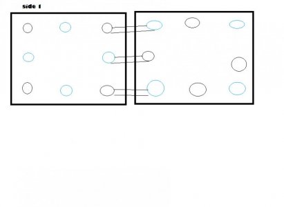
The issue i came up with getting it all down from vague idea to more concrete example was that i would have wanted to place the cross pipes above the tank keeping it all as simple as possible. You'd bunch up half the pipes near the front and half near the back to prevent lighting interference, but it still leaves the pumps up above the tank. And at least as i'm aware these sorts of pumps can't self prime like pool pumps, so... no go. You could run them under the tank though, i'd have the pumps intake point under the tank and go up and over to the far box, the outlets point up into the manifolds on the near box. Half the pumps on each side. Rows of pumps sitting on both sides of the tank like that might even look quite neat. The holey boxes would just be drilled enough to make up the combined area of half the pumps' intakes plus some extra for growth/buildup, sized and spaced to cover as much of the area as wanted. Some extra depth of straight/checkered baffles after the holes would probably help this as much as it helps props become more laminar sooner. Basically, a large square showerhead at each end with 6 pumps powering it in each direction.
Like this rendering:
The greens would be intakes, reds outlets. Only shown with a 8 pump configuration for simplicity sake. Live rock and corals omitted for file size issues... And stuff.


