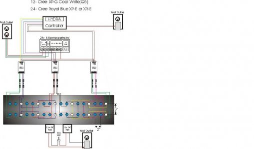
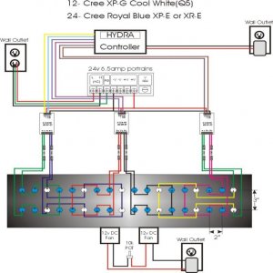
Led the complete plan

TheShadow

New member
attachment.php


Sorry 1st attempt at this
If someone would care to tackle any or all questions please start solution with the appropriate number. In the end I will revise diagram with all the correct information.


1)Are the number of LEDS and wiring correct per circuit
2)What ohm resister if any and should a fuse be added if so what size and were
3)Are the cat4101 drivers wired correct to the LEDS
4)Are the cat4101 drivers wired correct to the power supply
5) Is the power supply the correct size for the setup
6)Is power supply wired to system correct
7)Is the hydra wired correctly to the drivers
8)What size power supply is required for the hydra
9)Are the fans wired correctly and is it the write pot
10)Also can the fans be controlled by hydra if so how
11)Can fans be controlled by temp if so how
 

Attachments

  • LedPlan.jpg
    LedPlan.jpg
    32.3 KB · Views: 29
+1 for the above answer.

You might want to look at the "LED Color Aesthetics: The Emperor’s got no clothes. Or does he? " thread. People are talking about the use of cree cool white LEDs, and how the colour is not what they expected...
I just built a small 12 LED test rig using cree cool white and royal blues, and I think the colour looks terrible. I'm going to change most or all the whites to natural whites.

On a side note, what program did you use for your diagram? It looks very nice -a but small to read, but nice :)
 
Last edited:
1)Are the number of LEDS and wiring correct per circuit
Yes
2)What ohm resister if any and should a fuse be added if so what size and were
Neither needed, but a 1 ohm might make measuring current easier.
3)Are the cat4101 drivers wired correct to the LEDS
Can't tell and depends on the circuit board, but probably
4)Are the cat4101 drivers wired correct to the power supply
See 3
5) Is the power supply the correct size for the setup
May only allow 900ma oer string watch the heat
6)Is power supply wired to system correct
I looks like it
7)Is the hydra wired correctly to the drivers
Not sure the Hydra has 6 PWMs and you need a ground line probably
8)What size power supply is required for the hydra
12 volts I think 1 or 2 amps is probably good
9)Are the fans wired correctly and is it the write pot
Why a pt?
10)Also can the fans be controlled by hydra if so how
Probably, but I don't know
11)Can fans be controlled by temp if so how
Yes, you need some know how :) which I am lacking at the momeny
 
9)Are the fans wired correctly and is it the write pot
Why a pt?
How would you control the fans to turn off at night?
 
5) Is the power supply the correct size for the setup
May only allow 900ma oer string watch the heat
What is the correct supply and will the 3XCat4101 only allow 1 amp max? "watch the heat" for the power supply or the LEDs?
 
A fan on off you could just use a switch. There are circuits to control the speed based on heat, but I am not familiar with those and it may require a processor.

kcress recommends using 80% of a power supply. Using more and it may get to hot. There are six strings of LEDs and yes the CAT only does upto 1 amp. So 6 amps maximum. Ideally that would be a 7.5 amp supply or larger. A fan on the power supply might solve the problem also and it may not be one. You will have do decide.
 
Could I just get 2 power supplies 24v 6.5amp put 2 cat4101 on one and 1 on the other maybe use it to power the fans

Also what is the math you use to figure this
forward voltage(if so what is the fv for these LEDs?)
 
forward voltage is a function of the current through the LEDs. See the data sheet for the best guess.

Only 3 CATs. I thought the drawing showed 6. No the cat cannot power a fan.
 
technical questions aside. That LED combo/layout/spacing will not blend well.

The LED Color Aesthetics thread on RC is a little behind. You would be better off checking out the one over at nano-reef.
 
ordered the LEDS some time back but I planed on screwing them down put them on dimmers to play with colors then mix and match as RC and I catch up.

TheFishMan65 with your 8 board Cat4101. Wouldnt you need a power supply rated at 24v 10amp so you could run it at %80 percent or 8amps max?
 
Yes, meanwell makes a 12 amp IIRC that I found on ebay. That is also assuming I want 8 string at 1 amp. Right now I am only running 500ma so the 6.5 would work also.
 
Control the fans with the Hydra. Youll reference a temp sensor in the fins of the heatsink and tell the controller essentially

At temp X turn on 50%
IF temp X increases go to 60%
IF temp X increases go to 70% ect
IF temp > some value turn off lights

there are a few examples floating out there with example for code.
 
Found this now if I can figure out how to apply it to choose the right power supply

How to calculate what LED driver parameters are needed
Calculation of Maximum number of LEDs connected in series
EXAMPLE 1: To calculate the maximum number of LEDs that can be safely connected in series to a constant current LED driver use the maximum output voltage of the driver divided by the forward voltage of each LED.
If Vout max = 30VDC, and the Vforward = 3.0V, then the maximum number of LEDs is 30/3 = 10.A total of 10 LEDs can be connected in series with the constant current LED driver.
To select the required output current of the driver, consult the specification sheet for the LED used for the optimal current. Simply select an LED driver with the same optimal LED current.
 
If you're using a CAT4101 then calculating the max LEDs per driver (i.e. per IC) is pretty easy. The CAT4101 has a max voltage of 25v, so most people use them with common 24v supplies. This means 6 or 7 typical LEDs, depending on your choice of LED and the drive current. Keep in mind that the CAT4101 is fairly sensitive to voltage drop (i.e. the difference between input voltage and output voltage) so you want to tune the supply to the drivers after it's built.
 
dose the 3XCat4101 board dim all three cat4101 circuits or each cat4101.
can you tell me dose Thefishman65 8 board dim each Cat4101 or the whole board
 
My understanding is that the 3xCAT has one dimming channel, but this is just from memory.

My board was designed for 4 channels (second generation), but could do six by soldering wires where jumpers are supposed to go. It has two sides which basically duplicate each other. So there is one PWM that goe to string A and B, a second that goes to C and D can be selected with a jumpber to use either channel. Or solder a wire in and it would be its own channel.

Now it would be pretty easy to lift the pin on a CAT so each could have its own PWM.
 
Back
Top