You are using an out of date browser. It may not display this or other websites correctly.
You should upgrade or use an alternative browser.
You should upgrade or use an alternative browser.
Led the complete plan
- Thread starter TheShadow
- Start date
TheFishMan65
New member
There are pictures of my rev 1 board in my album. Do you want a FTS or what? I am a little confused.
TheShadow
New member
I apologize for the confusion. I have been reading these forums for months trying to get a handle on this project. (Which would not be possible without any of you)
Some patterns are beginning to emerge. I am not alone in my understanding so little.
The only way I can help all of those trying to understand this it to be the dumbest individual attempting this project.(not a far stretch)
If you can walk me through it step by step others could use this to complete there projects without bothering you guys with what you consider 1st grade questions
You guys are running; some of us are barely crawling
Trust me I hate asking these questions but I have no were else to turn.
Again please stick with me.
TheFishMan65
New member

TheFishMan65
New member
I am not sure that link is good - I can't seem to load the picture.
TheFishMan65
New member
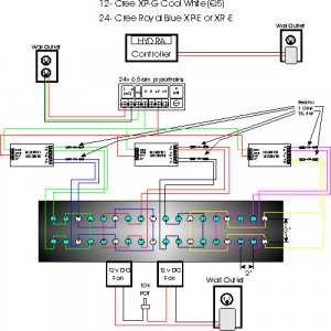
Move the whites to the same board (center ?) IIRC the 3x board has only one PWM input. You want to be able to control the color separetly.
No pot on the fans. Are tehy 12 volt and a 24 volt supply. If the LED current is low enough save some money and use the same poer supply.
No pot on the fans. Are tehy 12 volt and a 24 volt supply. If the LED current is low enough save some money and use the same poer supply.
TheShadow
New member
I put the leds on the drivers from left to right in order to possiply simulate sunrise and sunset with the PWM. Is this the wrong idea?. also without a pot on fans they will run at full all the time(12v) will that be needed?
If I go with your board would I not go from these 3 PWMs to 4 PWMs alowing more control of sunrise sunset?
If I go with your board would I not go from these 3 PWMs to 4 PWMs alowing more control of sunrise sunset?
TheFishMan65
New member
The pot means you need to be thre to adjust them. Forget and leave them low and you may (or might not) have problems).
Most people seem to raise the blues then the whites for sunset. My board could go to 6 with minor changes, but finding a controller that has 6 PWM maybe more difficult.
Most people seem to raise the blues then the whites for sunset. My board could go to 6 with minor changes, but finding a controller that has 6 PWM maybe more difficult.
TheFishMan65
New member
That is what I will do (right now they just go on and off). I also think most people are doing that. I have heard the east to west mentioned, but I have not heard of anyone actually implementing it. In terms of real life IMHO the four to eight feet of ocean we are simulating will not see different level of sunrise or sunset. Also as mentioned I don't know of any controller that handle more than 4 channels, doesn't mean there are not any.
TheFishMan65
New member
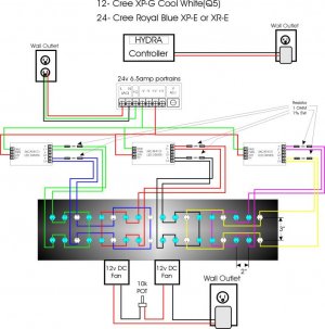
From most controllers (I'll more familiar with the Hydra) you can drive several CAT4101s with a PWM. I think the limit was near 10, I would need to look that up. So you could get by with one PWM going to all three boards or connected to all PWMs on my board. In the 3 board version the maximum (with out board modification) I believe is 3 (one for each board). With my board the maximum (without any modification) is 4.
I just noticed in your diagram that you are missing a 5 volt supply to the CAT4101 boards. that same 5 volts can go to PWM (for always on) until you get your controller up and running.
I just noticed in your diagram that you are missing a 5 volt supply to the CAT4101 boards. that same 5 volts can go to PWM (for always on) until you get your controller up and running.
TheShadow
New member
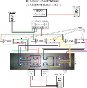
If I am going to dim lights using the Hydra I will need to use two PWMs? one for the 2blue boards and one for the white boards correct
"I just noticed in your diagram that you are missing a 5 volt supply to the CAT4101 boards" Not sure how to do this yet trying to get these pieces together 1st.
"I just noticed in your diagram that you are missing a 5 volt supply to the CAT4101 boards" Not sure how to do this yet trying to get these pieces together 1st.
Stevemarci
New member
Hydra
Hydra
Is the hydra controller out yet?
Hydra
Is the hydra controller out yet?
TheFishMan65
New member
I actually believe the Hydra could supply the 5 volts. Or you could find a separate supply.
PM me your email. I will send you some information on my board.
PM me your email. I will send you some information on my board.
Similar threads
- Replies
- 4
- Views
- 2K
- Replies
- 3
- Views
- 225
- Replies
- 0
- Views
- 108
- Replies
- 2
- Views
- 126
- Replies
- 39
- Views
- 837