theatrus
100-mile-commuter
http://www.clippard.com/part/EV-2-12-H
12V, normally closed two port 25psi standard seals with the wire leads
12V, normally closed two port 25psi standard seals with the wire leads
") ) planted tank - pretty sure I'm at 10psi. Ca reactor is set to 12 psi.
) planted tank - pretty sure I'm at 10psi. Ca reactor is set to 12 psi. I run a CO2 system through a diffuser in a (not very good
The good news is the 50 and 105psi versions are the same price - I wonder if the springiness of the spider and possible noise is the only difference? Or is there any difference except testing?
Sneak peak: yes it does work. Basic skills with 555 timers confirmed
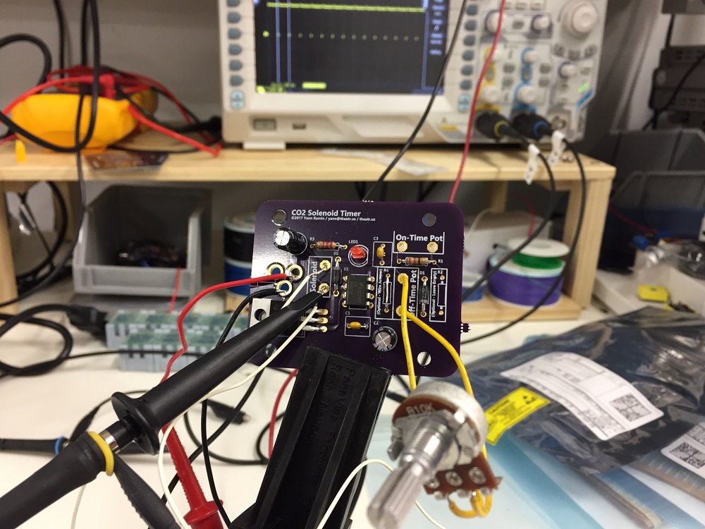
More details later
") also how does one build a circuit board ?
also how does one build a circuit board ?Where did you get that board, I looked for 555 timer and they are 0 - 9999 seconds delay timers, I am not sure if they are going to work..
Good info, i would buy your kit.
Sent from my SM-N910T using Tapatalk
Ok, just to put it in words..
The "on" time is now fixed at 30ms..(curious as to what it was at 0 ohms)
The # of on times (per minute?) is set by the pot....