You are using an out of date browser. It may not display this or other websites correctly.
You should upgrade or use an alternative browser.
You should upgrade or use an alternative browser.
Must-haves for EASY DIY controller?
- Thread starter der_wille_zur_macht
- Start date
der_wille_zur_macht
Team RC
Congrats and welcome to a whole new world.
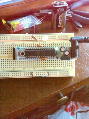
A few months ago I switched all my RBBBs over to plain old straight (vertical) headers for the FTDI instead of the 90 degree bent headers, because if you use a bent header and you try to put a cable or breakout on the header when it's on a breadboard like that, it can interfere with other stuff on the board. Just a thought.
A few months ago I switched all my RBBBs over to plain old straight (vertical) headers for the FTDI instead of the 90 degree bent headers, because if you use a bent header and you try to put a cable or breakout on the header when it's on a breadboard like that, it can interfere with other stuff on the board. Just a thought.
ZenMastr1968
New member
Yah, good call.... I might switch it. I took your advice and picked up a package of m/f headers from moderndevice so I have some.
terahz
1x10^12 Hz
Hmm, something is not right in the PH circuit. The 7660 chip is drawing almost 300ma and gets very very hot. Everything else draws another 200ma, so with all ICs populated and without the LCD I get a current use of a bit under 500ma which is a lot! It is getting a bit late today but I'll try to see what's wrong and will post back.
EDIT: BTW max input voltage for the 7660 is 10V, so 12V psu will not work:
"V+ Power-Supply Positive Voltage Input. (1.5V to 10V). V+ is also the substrate connection."
EDIT2: for some reason the 7660 puts out only -2.8V. It almost feels like it is in low voltage mode, but I don't see P6 being connected to anything.
Last edited:
TeraHz,
you should have bought the 7660A. This accepts up to 12V. The clean 7660 goes only up to 10V max input.
the reason you get only -2.8V is because you are missing a capacitor on the negative output. Place a 10uf capacitor with its minus on pin 5 and you will get what you want.
cheers,
Marian
PS. Make sure you have the capacitors correctly installed on the negative side and mind that 7905 has a different pin config than 7805.
Last edited:
der_wille_zur_macht
Team RC
TeraHz,
you should have bought the 7660A. This accepts up to 12V. The clean 7660 goes only up to 10V max input.
My fault! I meant to spec the 7660A but it clearly slipped my mind.
In the meantime we should be OK with 9v supplies. . .
I haven't soldered that portion of the circuit yet, I will hopefully get to it this weekend.
terahz - the current draw you're quoting - is that with the ENTIRE board populated? If so, the ENC chip must be very hungry. I have everything but the ENC and the pH section and I'm only drawing like 60 mA.
terahz
1x10^12 Hz
Yep, that's ok, I'm using a 9V psu for now, I was just pointing out that the spec'ed part goes up to 10V.you should have bought the 7660A. This accepts up to 12V. The clean 7660 goes only up to 10V max input.
C31 is there. The problem initially was C30 (0.1uf) being in between C31 (10uF polarized) and pin 5 I believe. DWZM probably put it there by mistake because it is not in the datasheet nor the schematic I have for the PH board.the reason you get only -2.8V is because you are missing a capacitor on the negative output. Place a 10uf capacitor with its minus on pin 5 and you will get what you want.
Yep, I think that's factored. I checked the chip itself with two caps as per the datasheet and it works excellent when it is not in a circuit. I think removing C30 fixed some of the issue. It started outputting -4.5V still not the -9 it is supposed to.PS. Make sure you have the capacitors correctly installed on the negative side and mind that 7905 has a different pin config than 7805.
After the 7660 was was fixed, now the entire board draws about 220mA. Most of it from the Ethernet chip. Without it, I believe it is at about 60mA. It is very likely something is wrong in that area to cause that much current, but hey that's why it is prototyping phaseSomething is wrong. Your pH board draws way to much. My whole Mega with 2 analog and 16 digital pins + ORP circuit + LCD goes around 400 mA !
")
Thanks Marian
My fault! I meant to spec the 7660A but it clearly slipped my mind.
In the meantime we should be OK with 9v supplies. . .
Yeah np. 9V is fine too. It will be easier on the negative converter.
Yes, that is the entire board. The ENC is really driving it up. PH circuit is very low current when it worksterahz - the current draw you're quoting - is that with the ENTIRE board populated? If so, the ENC chip must be very hungry. I have everything but the ENC and the pH section and I'm only drawing like 60 mA.

I'll continue tonight after work and report. After i removed C30 something else broke. Not sure what, but now GND to GND has 7V lol. Continuity check beeps for a split second and then doesn't detect a short. Almost like a cap is being charged/discharged and creates the short between +5V and GND.
der_wille_zur_macht
Team RC
Reviewing the datasheet and circuit for the 7660. Maybe I'll try to solder mine at lunch because this is a curious problem. Also wondering if the problem could be with the 7905 or a short elsewhere. . .
der_wille_zur_macht
Team RC
Hold the presses! I think the outline for the 7905 is backwards. This is the datasheet for the part I spec'd:
http://61.222.192.61/mccsemi/up_pdf/MC79L05BP(TO-92).pdf
The diagram showing pinout for the TO-92 case is pretty arbitrary, it's hard to tell the orientation of the device (are we looking at the bottom or the top?)
Now look at this, which is the pin-compatible reg from Fairchild:
http://www.fairchildsemi.com/ds/LM/LM79L05A.pdf
Or this, from ST:
http://www.st.com/stonline/books/pdf/docs/2511.pdf
Pin 1 is clearly identified in these two datasheets with respect to the flat side of the case, and is OPPOSITE how I positioned it on the circuit.
ZenMastr1968
New member
Not to deter from the recent activity, but what do you guys use for desoldering methods??
As with any learning experience, I think I've hosed my RBBB while trying to remove that right angle header for the programming interface using desoldering wick....I think I peeled the pads off the board. I'm trying to decide if I can use another method to remove the parts and just buy a new board or just scrap it and get a whole new kit.
On a side note, I was able to upload the example LCD Blink the other day and just wired it back up and the LCD is working....
Last edited:
der_wille_zur_macht
Team RC
Hot iron and braid to get most of the solder off, plus a solder sucker for getting it out of annoying through-holes that get clogged up.
Often you have to decide if you want to save the board or the part. The trickiest situations are where you want to save BOTH. For instance, getting your old header off, you can use wire clippers to cut the plastic between each of those six pins, then pull them off one by one. The header is ruined but the board should be fine.
Modern Device sells bare RBBB PCBs for a few bucks if you want to swap things. Luckily the 328 is socketed so it pops out and moves over. Worst case, you can replace the rest of the parts (the few caps and resistors) on the board for maybe a buck or two, so it's no big deal to "rebuild" one of them.
Or, if you really ruined the pads for that header and you want to be super-economical, you could just wire your FTDI breakout board to the correct pins on the device itself (reset, rx, tx, 5v, GND). The header is just a convenience to bring those pins next to each other, there's no special magic.
ZenMastr1968
New member
Hot iron and braid to get most of the solder off, plus a solder sucker for getting it out of annoying through-holes that get clogged up.
Often you have to decide if you want to save the board or the part. The trickiest situations are where you want to save BOTH. For instance, getting your old header off, you can use wire clippers to cut the plastic between each of those six pins, then pull them off one by one. The header is ruined but the board should be fine.
Modern Device sells bare RBBB PCBs for a few bucks if you want to swap things. Luckily the 328 is socketed so it pops out and moves over. Worst case, you can replace the rest of the parts (the few caps and resistors) on the board for maybe a buck or two, so it's no big deal to "rebuild" one of them.
Or, if you really ruined the pads for that header and you want to be super-economical, you could just wire your FTDI breakout board to the correct pins on the device itself (reset, rx, tx, 5v, GND). The header is just a convenience to bring those pins next to each other, there's no special magic.
Yah, stupid be decided to try to save both for some reason. It wasn't until too late in the process that I figured out I could just slide the plastic piece off the pins and get them to fall out one at a time... I tried uploading a new sketch to the RBBB and it's not working. I may try hot wiring it and see.
Just curious - it is always kind of tricky to get the sketch uploaded to the boards? I tried several times yesterday and it wouldn't upload while hooked up for the LCD test I was trying, but when I pulled all the wires out it did upload (as I got a hello world message on the display once I got the contrast figured out). I just tried it both ways and nothing (after destroying the board at the header).
der_wille_zur_macht
Team RC
Uploading shouldn't be a problem. The issue might be wiring problems causing the AVR not to run correctly (a short, etc.) It's usually a good idea to not use the tx and rx pins of the serial port (digital pins zero and one) for anything external because that CAN cause issues, if the circuit is connected during upload.
terahz
1x10^12 Hz
Hold the presses! I think the outline for the 7905 is backwards. This is the datasheet for the part I spec'd:
http://61.222.192.61/mccsemi/up_pdf/MC79L05BP(TO-92).pdf
The diagram showing pinout for the TO-92 case is pretty arbitrary, it's hard to tell the orientation of the device (are we looking at the bottom or the top?)
Now look at this, which is the pin-compatible reg from Fairchild:
http://www.fairchildsemi.com/ds/LM/LM79L05A.pdf
Or this, from ST:
http://www.st.com/stonline/books/pdf/docs/2511.pdf
Pin 1 is clearly identified in these two datasheets with respect to the flat side of the case, and is OPPOSITE how I positioned it on the circuit.
I had the same issue with the PH board, initially I had read the datasheet backwards so I had to solder the 7905 on the bottom
. I think you have it correct though. The v1.05 of the PH board circuit has the correct layout, if you want to compare it with that. I tried to compare it with the PH board I have, but I was half asleep so my check can't be trusted. Will recheck tonight. I might have killed the 7905 with the high current initially so that could be the short problem on my board. I'll change that tonight as well.
It is really strange, there is a short on the board and i can read 7V from GND to GND!, but for some reason the current doesn't go up, so it doesn't act like a normal short (where things start to smoke/explode)
Man I wish I was at home today
der_wille_zur_macht
Team RC
I think you have it correct though
You think I have it correct on the PCB, or correct in my quote above?
I'm going to breadboard the negative supply and see what happens. I have a few extra 7905's but hopefully I won't need them.
Which GND points were you measuring a 7v difference across?
terahz
1x10^12 Hz
On the PCB.You think I have it correct on the PCB, or correct in my quote above?
From memory: the GND row of pins and the GND pad of the 7805.Which GND points were you measuring a 7v difference across?
der_wille_zur_macht
Team RC
On the PCB.
But look at the image, upper right, first page of this:
http://www.fairchildsemi.com/ds/LM/LM79L05A.pdf
Pin one, being GND, is backwards from how I have it on the PCB.
Anyways I'll breadboard it and see what happens. As soon as I get off this conference call. . . :lol:
Similar threads
- Replies
- 6
- Views
- 2K
- Replies
- 0
- Views
- 1K
- Replies
- 2
- Views
- 268