You are using an out of date browser. It may not display this or other websites correctly.
You should upgrade or use an alternative browser.
You should upgrade or use an alternative browser.
Must-haves for EASY DIY controller?
- Thread starter der_wille_zur_macht
- Start date
HippieSmell
Occupy Reef Central
Has anyone checked out the Reef Angel? I just bought one and it might be appealing for some of you who would like to expand or improve upon an already existing controller.
Obi-dad
Active member
One more question, in looking at the schematics, is pin 5 of the mag jack supposed to be connected to the center of the two resistors and the cap?? I found this site that outlined the same Ethernet chip for a different processor, but the circuit was similar
http://www.kandi-electronics.com/uCEthernet/Ethernet_1.aspx
on page 2 they have this schematic http://www.kandi-electronics.com/uCEthernet/uC%20Ethernet1.pdf and they show pin 5 connecting similarly to pin 4...
Any thoughts on this? is the Ethernet circuit working on anyone who has gotten that far with the way it is? I know it's not shown as connected on the sample circuit on the datasheet....
Zen, did you get an answer from anyone on your questions (in PM or other contact)? Inquiring minds want to know.
Last edited:
Absolutely incredible work folks. I've been an electronics geek since I was 8 years old! That was a LONG time ago. That said, I have yet to play with any of the microcontrollers. That will now change.
Looking forward to future updates.
BTW, I'll be using this controller for a high-tech freshwater planted aquarium.
GW
Looking forward to future updates.
BTW, I'll be using this controller for a high-tech freshwater planted aquarium.
GW
stephenrwright
New member
GW,
I am the same way, use to play with electronics when I was a kid, didnt get much past my single board 1802 computer, "grew up" and became a software geek, 30 years later this hardware stuff is neat, working on a LED controler with a arduino pro mini, real time clock, LCD display and a few temp sensors. Everyone here is great, there is alot of resorces out there.
The TinyCLR.com FEZCobra looks like the next one I will try out, being a dot net developer.
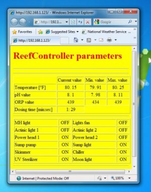
just finished the Ethernet part for my approach. Here is a picture of the webpage:
cheers,
Marian
PS. The code has already been posted here: http://reefprojects.com/w/phpBB3/viewtopic.php?f=8&t=298
cheers,
Marian
PS. The code has already been posted here: http://reefprojects.com/w/phpBB3/viewtopic.php?f=8&t=298
Attachments
ZenMastr1968
New member
Zen, did you get an answer from anyone on your questions (in PM or other contact)? Inquiring minds want to know.
No, and I haven't been able to try it out yet - moving so I hope to get back to looking at it soon.
der_wille_zur_macht
Team RC
Haven't tried Ethernet myself yet, either, though as MaLi pointed out there are libraries out there for this chip so it shouldn't be much of a struggle. The farthest I got was downloading the most promising library and troubleshooting it to the point that I could get an example sketch to compile, I have yet to put it on the hardware. If people are super curious I can put the code on the google site.
terahz
1x10^12 Hz
I worked a bit on the relay part of the controller so here is the progress.
2x opto-isolated 10A 4 relay board from futurlec
http://www.futurlec.com/Opto_Relay_4.shtml
1x American DJ power strip
http://www.amazon.com/American-DJ-P...8&s=musical-instruments&qid=1278899261&sr=8-1
1x MCP23008 port expander (same as on the controller)
http://mouser.com/ProductDetail/Mic...3008-E-P/?qs=sGAEpiMZZMvcAs5GUBtMdVgPLCS8TUZv
The nice thing about the relay boards is that they come with cables and 2 can be chained together so that you have only one 10 pin cable (8 channels, 5v, gnd)
Most of the work is in the Power strip really. First had to open it. The lid has 4 metal screws, 2 on each side:

It is fairly neat inside, and the nice plugs allow for easy modification:

I interrupted the short black single wire. That is the negative/return/neutral whatever it is:

Since most of the plugs are not well crimped, it is very easy to pull the wire out of them:

I used a metal scribe to expand the pins a bit so I can crimp the longer wire.
The power strip uses 18AWG wire so that's what I used too. I used 8x 6ft pieces to make this:

Note that half of the terminals are smaller, so when/if you do this pay attention to pair a small one with a big one.
Connecting the wires back:

After that, I cut each wire exactly in the middle to end up with 16 wires. I tried to braid them, but it's no easy task to braid with 16 stiff wires (no, they are not solid core, just very stiff). I drilled/filed a cut next to the power cord and used a couple of zip ties to limit the movement.

In the end I ended up with 8 pairs of wire that can be connected to the relays, which are controlled by the Hydra via the MCP port expander.

I almost forgot, make sure you label the wires BEFORE you start braiding, or it will take a while to figure out which is which (unless you have 9 colors of wire). If you do forget, plug the power cord in one of the outlets and turn ON only that outlet. With a multimeter on continuity mode check which two wires complete a circuit. That is your pair for that outlet.
I've done some of the programming for controlling the relays, but have some more work to do.
It worked out pretty well. I think 8 outlets will be enough for me (1 power head, 1 return, 1 heater, 1 skimmer, 2 lights, 1 top-off) but the nice thing is you can add quite a lot of these to a hydra by just getting another set of components.
Total cost for 8 controlled 10A outlets comes to a bit over $60. Not bad imho.
2x opto-isolated 10A 4 relay board from futurlec
http://www.futurlec.com/Opto_Relay_4.shtml
1x American DJ power strip
http://www.amazon.com/American-DJ-P...8&s=musical-instruments&qid=1278899261&sr=8-1
1x MCP23008 port expander (same as on the controller)
http://mouser.com/ProductDetail/Mic...3008-E-P/?qs=sGAEpiMZZMvcAs5GUBtMdVgPLCS8TUZv
The nice thing about the relay boards is that they come with cables and 2 can be chained together so that you have only one 10 pin cable (8 channels, 5v, gnd)
Most of the work is in the Power strip really. First had to open it. The lid has 4 metal screws, 2 on each side:
It is fairly neat inside, and the nice plugs allow for easy modification:
I interrupted the short black single wire. That is the negative/return/neutral whatever it is:
Since most of the plugs are not well crimped, it is very easy to pull the wire out of them:
I used a metal scribe to expand the pins a bit so I can crimp the longer wire.
The power strip uses 18AWG wire so that's what I used too. I used 8x 6ft pieces to make this:
Note that half of the terminals are smaller, so when/if you do this pay attention to pair a small one with a big one.
Connecting the wires back:
After that, I cut each wire exactly in the middle to end up with 16 wires. I tried to braid them, but it's no easy task to braid with 16 stiff wires (no, they are not solid core, just very stiff). I drilled/filed a cut next to the power cord and used a couple of zip ties to limit the movement.
In the end I ended up with 8 pairs of wire that can be connected to the relays, which are controlled by the Hydra via the MCP port expander.
I almost forgot, make sure you label the wires BEFORE you start braiding, or it will take a while to figure out which is which (unless you have 9 colors of wire). If you do forget, plug the power cord in one of the outlets and turn ON only that outlet. With a multimeter on continuity mode check which two wires complete a circuit. That is your pair for that outlet.
I've done some of the programming for controlling the relays, but have some more work to do.
It worked out pretty well. I think 8 outlets will be enough for me (1 power head, 1 return, 1 heater, 1 skimmer, 2 lights, 1 top-off) but the nice thing is you can add quite a lot of these to a hydra by just getting another set of components.
Total cost for 8 controlled 10A outlets comes to a bit over $60. Not bad imho.
TheFishMan65
New member
I have been trying to figure out a inexpensive way to do this. Thanks for doing my work!
Obi-dad
Active member
I worked a bit on the relay part of the controller so here is the progress.
2x opto-isolated 10A 4 relay board from futurlec
http://www.futurlec.com/Opto_Relay_4.shtml
1x American DJ power strip
http://www.amazon.com/American-DJ-P...8&s=musical-instruments&qid=1278899261&sr=8-1
1x MCP23008 port expander (same as on the controller)
http://mouser.com/ProductDetail/Mic...3008-E-P/?qs=sGAEpiMZZMvcAs5GUBtMdVgPLCS8TUZv
The nice thing about the relay boards is that they come with cables and 2 can be chained together so that you have only one 10 pin cable (8 channels, 5v, gnd)
Most of the work is in the Power strip really. First had to open it. The lid has 4 metal screws, 2 on each side:
It is fairly neat inside, and the nice plugs allow for easy modification:
I interrupted the short black single wire. That is the negative/return/neutral whatever it is:
Since most of the plugs are not well crimped, it is very easy to pull the wire out of them:
I used a metal scribe to expand the pins a bit so I can crimp the longer wire.
The power strip uses 18AWG wire so that's what I used too. I used 8x 6ft pieces to make this:
Note that half of the terminals are smaller, so when/if you do this pay attention to pair a small one with a big one.
Connecting the wires back:
After that, I cut each wire exactly in the middle to end up with 16 wires. I tried to braid them, but it's no easy task to braid with 16 stiff wires (no, they are not solid core, just very stiff). I drilled/filed a cut next to the power cord and used a couple of zip ties to limit the movement.
In the end I ended up with 8 pairs of wire that can be connected to the relays, which are controlled by the Hydra via the MCP port expander.
I almost forgot, make sure you label the wires BEFORE you start braiding, or it will take a while to figure out which is which (unless you have 9 colors of wire). If you do forget, plug the power cord in one of the outlets and turn ON only that outlet. With a multimeter on continuity mode check which two wires complete a circuit. That is your pair for that outlet.
I've done some of the programming for controlling the relays, but have some more work to do.
It worked out pretty well. I think 8 outlets will be enough for me (1 power head, 1 return, 1 heater, 1 skimmer, 2 lights, 1 top-off) but the nice thing is you can add quite a lot of these to a hydra by just getting another set of components.
Total cost for 8 controlled 10A outlets comes to a bit over $60. Not bad imho.
Nice job, looks great. I will be copying your design :rollface:
hello everybody,
Just saw this thread and I am pretty impressed. I just read the first 5 pages right now and you guys were talking about relays to turn ON and OFF pump, chiller, lights .....
Why are you not using Triac ? Very easy to drive and you don't have the mechanical problem like the relays can have if you switch to fast (like if you want to do a wavemaker)
ludnix
New member
hello everybody,
Just saw this thread and I am pretty impressed. I just read the first 5 pages right now and you guys were talking about relays to turn ON and OFF pump, chiller, lights .....
Why are you not using Triac ? Very easy to drive and you don't have the mechanical problem like the relays can have if you switch to fast (like if you want to do a wavemaker)
I'm still new to electronics, could you post a link to a triac that would be appropriate for the kinds of loads we would be using in an aquarium controller?
der_wille_zur_macht
Team RC
People can use whatever they want to switch loads - personally, I'm concentrating the design effort here on the controller itself, using I2C or some other protocol to communicate with a port expander on a separate relay board, which people can design however they want.
My approach will probably just be to copy terahz's post above. It's relatively cheap, should handle the things we need to switch, and, best of all, it keeps me from having to fool with mains power on a PCB design, which is something that shouldn't be underestimated for inexperienced hobbyists IMHO.
My approach will probably just be to copy terahz's post above. It's relatively cheap, should handle the things we need to switch, and, best of all, it keeps me from having to fool with mains power on a PCB design, which is something that shouldn't be underestimated for inexperienced hobbyists IMHO.
Like this one on digikey:
http://search.digikey.com/scripts/DkSearch/dksus.dll?Detail&name=497-7189-5-ND
Just need to put an optoisolator before ...
Just concern about relay with the wavemaker part(the relay will not last forever).
http://search.digikey.com/scripts/DkSearch/dksus.dll?Detail&name=497-7189-5-ND
Just need to put an optoisolator before ...
Just concern about relay with the wavemaker part(the relay will not last forever).
terahz
1x10^12 Hz
OTCHU, Triacs will work too, I picked the mechanical relays because I liked the relay boards posted above. Otherwise I was halfway done with a SSR version of the mod (still have the relays here). As for a wavemaker, I don't plan to run one but if I did, it is easy enough to wire a separate SSR just for it as it can be driven directly from an arduino pin.
Really interesting thread. I actually have a 7 or so year old neptune that I use and like what those boys have done. Cost was a issue of course but its a one stop shop for everything which most of you are adding to your DIY controller it looks like.
Wonder how the cost would compare. Although I think that is hard to figure out because this is more of a hobby and its hard to put a dollar amount to your work. But its really cool reading this.
So my question I guess. Would it be possible to configure these to send a signal to a sprinkler valve / wired solenoid to turn it on and off? I was reading about the ocean motion 4 and 8 way devices and they are really nothing more than a wired solenoid from what I can tell. You could do a closed loop with these and achieve the same thing or even just use it for returns. I just do not know how they would react to salt water vs fresh which is what most use for irragation. I do know they are heavy duty though.
Second question or thought I guess. Would be cool for those of you doing the ethernet interface to have it automously broadcast temp, ph, or any other stat for that matter to a set location. Then create a gadget in windows to display it in real time.
Anyway great tech thread here.
der_wille_zur_macht
Team RC
Wonder how the cost would compare. Although I think that is hard to figure out because this is more of a hobby and its hard to put a dollar amount to your work. But its really cool reading this.
It's hard to do a cost comparison because the featuresets are much more different than it looks. But, if you chose every "option" on a Hydra, you might spend $150 - $200 and end up with the same functionality you get on a $500 - $1000 commercial product.
So my question I guess. Would it be possible to configure these to send a signal to a sprinkler valve / wired solenoid to turn it on and off? I was reading about the ocean motion 4 and 8 way devices and they are really nothing more than a wired solenoid from what I can tell. You could do a closed loop with these and achieve the same thing or even just use it for returns. I just do not know how they would react to salt water vs fresh which is what most use for irragation. I do know they are heavy duty though.
The beauty of DIY'ing a controller is that any time you ask "can it do X?" the answer is always YES, if you're willing to put the effort in to it. For turning different "things" on and off - valves, motors, pumps, etc. generally the worst case is you need a relay or some other buffer between the controller and the device. In most cases this is cheap and easy.
Second question or thought I guess. Would be cool for those of you doing the ethernet interface to have it automously broadcast temp, ph, or any other stat for that matter to a set location. Then create a gadget in windows to display it in real time.
Anyway great tech thread here.
Yes - the Ethernet interface would easily be able to do that. You can write a webserver to run on it, such that you can check specs from any web browser. The direction I've been planning on going is to put a tweeter client on it, and have it tweet alarms and stats to an account I will "follow" via email and/or SMS.
I think I've figured out - conceptually - how to get an Arduino to send text messages via Google Voice. There are some blog posts out there that have documented the form submissions necessary. The only trick is that there is some parsing of page source that needs to be done, and some session-related stuff (cookies, IIRC) that need to be sent. I've never written an HTTP client (especially not on an Arduino!), so I'd just have to work out how to do that stuff efficiently.Yes - the Ethernet interface would easily be able to do that. You can write a webserver to run on it, such that you can check specs from any web browser. The direction I've been planning on going is to put a tweeter client on it, and have it tweet alarms and stats to an account I will "follow" via email and/or SMS.
Twitter's web API probably has similar requirements; I could probably look at some library code for a Twitter library for Arduino to figure out how to do that stuff.
(I'd probably prefer alerts to go directly to SMS rather than be routed thru Twitter...)
The real challenge is finding the time to write the library.
der_wille_zur_macht
Team RC
There's already a generic library for the ENC chip, and (wonderfully) it includes several example sketches - a web server, a twitter client, etc. So I'm hoping we can just rip off that stuff. I've gotten all the examples to compile as part of my experimentation so far but haven't actually tried it (I don't have the ENC portion of the circuit soldered up yet!).
I'm leaning towards twitter because it's a generic "central location" on the internet. You can check it from any internet-connected PC or device, AND you can have it automatically send text, email, etc. So rather than having to implement a client for each of those purposes, or write my own "middleware" on a PC or something, I can just dump data on twitter and access it however I want once it's there.
I'm leaning towards twitter because it's a generic "central location" on the internet. You can check it from any internet-connected PC or device, AND you can have it automatically send text, email, etc. So rather than having to implement a client for each of those purposes, or write my own "middleware" on a PC or something, I can just dump data on twitter and access it however I want once it's there.
Similar threads
- Replies
- 6
- Views
- 2K
- Replies
- 0
- Views
- 1K
- Replies
- 2
- Views
- 143