Vancouver Reefr
New member
Hi Stage,
The break out boards i got from Sparkfun, They make working with the SMD stuff so much easier!! I found soldering them was not too bad, just take your time and keep your soldering iron tip clean.
I ended up using the Zetex ZXLD1362. Its a great little driver. 1A and up to 60V. Im driving 12 LED's of each string at 48V.
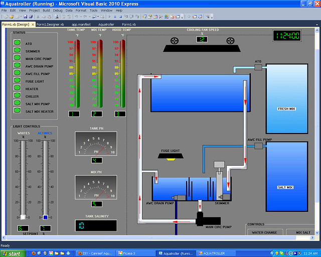
As for the programming i did most of it myself. I used alot of copy and pasting from other people's codes on the arduino forum and then adjusted it to suit my application. I used to program industrial PLC's and had never done an C before so i know my code is not anywhere near how it should be written. However i have written it to how i understand it and so far its working fine. Time will tell once im up and running to see if i have any bugs in it.
VR
The break out boards i got from Sparkfun, They make working with the SMD stuff so much easier!! I found soldering them was not too bad, just take your time and keep your soldering iron tip clean.
I ended up using the Zetex ZXLD1362. Its a great little driver. 1A and up to 60V. Im driving 12 LED's of each string at 48V.
As for the programming i did most of it myself. I used alot of copy and pasting from other people's codes on the arduino forum and then adjusted it to suit my application. I used to program industrial PLC's and had never done an C before so i know my code is not anywhere near how it should be written. However i have written it to how i understand it and so far its working fine. Time will tell once im up and running to see if i have any bugs in it.
VR
")