My Neptune Apex web interface compatible DIY reef controller

I went ahead and updated github with the latest code. I tested the ph stamp only. The orp is very similar to ph so I don't expect any problem. The conductivity, if anyone will use it, just capture the serial monitor output and email it to me so I can update the code.

I tagged this to v20140819

Change Log


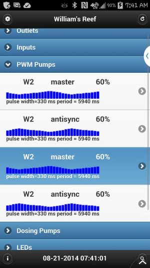
  1. Added support for up to 3 Atlas stamps.
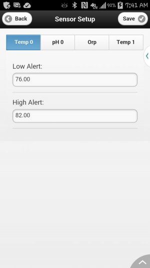
  2. Sensor setup page allows setting high and low alert values.
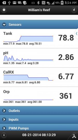
  3. Calibrate Atlas sensors in Sensor setup page.
  4. Fixed default outlet names for outlets 9-16.
 
I am going to start working on LED control this weekend. The plan is 6 channel PWM, as I see the full spectrum multichip LEDs come with 5 channels, so there is 1 extra channel for additional supplemental LEDs. There will also be 2 8bit PWM available for general use, like fan control.

I'm not sure yet what resolution I will use. I can go up to 16bit, but I don't think that is needed. I'm thinking 11 bit is the most efficient at about 2000 steps. The meanwell LDD drivers can take PWM frequency between 100-1000hz, I'll be using something closer to 1000hz.

Besides the standard ramp up/down, I will also include a solar cycle and moon phase feature. I'm thinking of doing more than just a sunrise/sunset, and will use the solar noon as the peak time.

I'm working on the solar astronomy formulas and trying to convert them to all integer calculations, since I probably will run the control in interrupt code just like what I did with the jebao pump control. Doing this in interrupt code allows me to change the duty cycle value down to the pulse. Even if a controller has a high resolution, if it is updating the pwm duty cycle at a longer interval, it will still not be as smooth as changing the duty cycle down to each individual pulse.

For instance, if pwm frequency is 1000hz, each pulse is 1ms. For loop based arduino program, if they update the ramp value from 1% to 2% in say 50ms (due to all the other code to be executed in the loop), the pwm transition is time 0 is 1%, then at time 50ms is 2%. If the ramp is done per pulse, then at time 0 is 1%, time 1 is 1.02%, time 2 is 1.04%, etc until it gets to 2% at time 50. This way, we are really using the resolution of the pwm. I think for loop based programs, the standard arduino 8 bit pwm at 980hz is perfect.
 
Last edited:
Tried the new code with only 2 temp probes and 1 ph probes and somehow the graph for the second temp is not there. Haven't tried on my tank with the 2 ph and orp probes yet just testing it out with my test setup.
 
The graph is based on data from sensor log. Go to logs section and view the sensor.log and see what data you get.
The log is once every 10 minutes. So if you just added the second temp sensor, you will need to wait about 10 minutes (it logs on the hour, 10 past, 20 past, etc) then check the sensor.log again.

I look at the sensor log and at first I had only one temp address put in and then added the second and somehow it wasn't graphing deleted the data with the one probe and now its working ok.
 
Also when I put this new code on the unit with the 2 ph and orp. I need one ph probe to control the calRx. Do I call #define CalRx like I have it now with the old code.
 
The is no outlet control for the second ph (only high and low value alerts).
you can easily add it as follows

create a new function (in Outlets.ino)

Code:
void checkCalRX(){
if (getAtlasAvg(phdata[1])>6.70)  _outletOn();
if (getAtlasAvg(phdata[1])<6.50) _outletOff();
}
<calrx><calrx> then in outletHandlerB function, add the line

Code:
<calrx><calrx></calrx></calrx>checkCalRX();
</calrx></calrx><calrx><calrx>after the line
Code:
<calrx><calrx></calrx>
checkAlarm();
</calrx></calrx></calrx><calrx><calrx>this will check once every 15 seconds. If you need a different checking interval, you can add a new if condition based on minnow and secnow for the current minute and second value.
The above code assumes your second ph probe is the one in your calrx.

</calrx></calrx>
 
now come to think of it, my ph calibration is only for ph7 and ph10. So you will need to calibrate that by loading the atlas ph sketch to calibrate for ph4 and ph7, then load the chauvet code again.
 
How will I now which outlet the ph will control. Do I do it like this
Code:
void checkCalRX(){
if (getAtlasAvg(phdata[1])>6.70)  _outletOn(CalXOut);
if (getAtlasAvg(phdata[1])<6.50) _outletOff(CalXOut);
}
this what I call the outlet in the old code to control the Reactor
and do I still have to define the CalRx in config.h
#define CalRX
 
If CalXOut is in your OUTLETDEFS define (in the correct outlet order) and is the outlet for controlling the calcium reactor, then that is correct.

I don't remember what/how you used CalRX define, but I think it is not needed anymore here.
 
Upload the new code last night. I have 2 pH, 1 Temp and 1 Orp probe hook up and also have 4 WP pumps hook up.

I had a power outage yesterday because of a bad storm that came. But when the power came back on one of my pH probe was reading wrong. Will see if it went out of Cal. today.

I notice that my Orp probe is reading 361 and the led on the atlas circuit is not flashing like the 2 pH circuits. Before I loaded the new code they all flash at the same rate.

The WP pumps I can't change what I put in the code to be on Auto. I had pump 0 to be in W1 and the rest to be in Else mode. I can change in the manual mode. Before I could program the mode in the code to what I wanted to be Auto.

In Sensors setup I don't see but 1 pH probe and I see a Temp 1 instead.


I had a compile error
Utils:129: error: 'SensorAlarm_t' was not declared in this scope
Utils:129: error: expected `;' before 'orpalert'
Utils:130: error: 'orpalert' was not declared in this scope

So I change SensorAlarm to SensorAlert in the Orp part in Utils and then it compile

I have the code running for now
 

Attachments

  • 2014-08-21-08-14-06.jpg
    2014-08-21-08-14-06.jpg
    44.8 KB · Views: 2
  • 2014-08-21-07-41-16.jpg
    2014-08-21-07-41-16.jpg
    55.3 KB · Views: 1
  • 2014-08-21-07-41-43.jpg
    2014-08-21-07-41-43.jpg
    23.1 KB · Views: 2
If CalXOut is in your OUTLETDEFS define (in the correct outlet order) and is the outlet for controlling the calcium reactor, then that is correct.

I don't remember what/how you used CalRX define, but I think it is not needed anymore here.

The added code works without the #define CalRX.
Thanks
 
Upload the new code last night. I have 2 pH, 1 Temp and 1 Orp probe hook up and also have 4 WP pumps hook up.

I had a power outage yesterday because of a bad storm that came. But when the power came back on one of my pH probe was reading wrong. Will see if it went out of Cal. today.

I notice that my Orp probe is reading 361 and the led on the atlas circuit is not flashing like the 2 pH circuits. Before I loaded the new code they all flash at the same rate.

The WP pumps I can't change what I put in the code to be on Auto. I had pump 0 to be in W1 and the rest to be in Else mode. I can change in the manual mode. Before I could program the mode in the code to what I wanted to be Auto.

In Sensors setup I don't see but 1 pH probe and I see a Temp 1 instead.


I had a compile error
Utils:129: error: 'SensorAlarm_t' was not declared in this scope
Utils:129: error: expected `;' before 'orpalert'
Utils:130: error: 'orpalert' was not declared in this scope

So I change SensorAlarm to SensorAlert in the Orp part in Utils and then it compile

I have the code running for now

You are using the latest code from github right? and you changed the EEPROMSIG value so the eeprom gets initialized right?

the sensors setup page does not look right. you only have one temp sensor right? The order of the tabs should be temp0..tempn, ph0...phn, orp, cond. So for your setup, the tabs should be temp0, ph0, ph1, orp.

If you load the atlas sketch for orp, what reading are you getting? What is a valid range of reading for orp.

I fixed the auto mode problem for pumps 2 and 3 in the latest code. Please describe the problem in a little more detail if you are still seeing a problem.
In your PWM pump screenshot. When pumps 1-3 are not master, they are sync or anti sync with reference to pump0. If they are master, they are operating independently. So you wanted pump2 to be the same as pump0, you can set that to sync. Setting pump2 to master will make it run independently.

I will fix the typo in utils.ino, and I'll update the calibration part of the code to have calibrate4 for ph, and probably two point calibration for conductivity as well.
 
Yes using the lastest code from github. I changed the EEPROMSIG. I was getting reading in the 400 range. I will check today when I get home to see what atlas sketch is getting.
This is what I put in the code for the pumps
Code:
#define PUMP0 {{_master,H1,128,0},{_master,W1,255,6},{_master,W1,255,8},{_master,W1,255,2},{_master,W1,255,8},{_master,H1,128,0}}
#define PUMP1 {{_sync},{_master,ELSE,255,10},{_master,ELSE,255,10},{_master,ELSE,255,10},{_master,ELSE,255,10},{_sync}}
//#define PUMP0 {{_master,H1,128,0},{_master,H1,128,0},{_master,H1,128,0},{_master,H1,128,0},{_master,H1,128,0},{_master,H1,128,0}}
//#define PUMP1 {{_master,H1,128,0},{_master,H1,128,0},{_master,H1,128,0},{_master,H1,128,0},{_master,H1,128,0},{_master,H1,128,0}}
#define PUMP2 {{_sync},{_master,ELSE,255,10},{_master,ELSE,255,10},{_master,ELSE,255,10},{_master,ELSE,255,10},{_sync}}
#define PUMP3 {{_sync},{_master,ELSE,255,10},{_master,ELSE,255,10},{_master,ELSE,255,10},{_master,ELSE,255,10},{_sync}}

I did notice that the flashing green light wasn't flashing for the Orp. Will clear memory and upload again.
 
your defines look fine. and you are seeing it run as shown in the screenshot you attached? Can you go to the pwm pump setup page to verify the program shows what is in your define?
 
your defines look fine. and you are seeing it run as shown in the screenshot you attached? Can you go to the pwm pump setup page to verify the program shows what is in your define?

No there show whats you have in the original code, and what I post in the last post is what I change them too. I can go in the pwm pump setup and change them.
 
No there show whats you have in the original code, and what I post in the last post is what I change them too. I can go in the pwm pump setup and change them.

if you edited config.h to what you shown, that should have been the default after eeprom is initialized. So it is not showing the correct pump mode even after you set it in setup page? Make sure you click save to exit the pwm pump setup page. If you connected a buzzer, you should hear the confirmation beep on successful save.

regarding the sensor setup page, does it still show like your screenshot now? if you have 1 temp, 2ph and 1 orp, the tabs must show temp0, ph0, ph1, orp. Maybe that's related to/causing the incorrect readings. I'll check the code again, but I know when I tested using test data, I was able to see the correct tabs.

regarding orp reading. I see the problem now. I am not calling updateAtlas(orpdata) from main loop. likewise same problem for cond. I will fix that when I get home. The 361 reading you see is the initial reading from when the orp was initialized.

If you want to fix this before I update github, just add the line
updateAtlas(orpdata);
right above the #ifdef _SONAR line in the Chauvet16.ino file.
 
Last edited:
Yes still reading the same, I will redo everything later today to see if it change and also go back to the old code to see if it come back. Will let you know
 
Back
Top