Questions on dimming LDD drivers

Jonviviano

New member
Hello all,

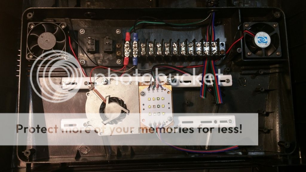
First I will apologize if this has been covered, I have had no luck using the search feature or google to answer a few questions. I am trying to update my knowledge on DIY led setups. I have a few setups using meanwell dimmable drivers, and a few setups with typhon controllers. My newest project wil include a Lumia 5.2 multichip and i would like to power it with a 5UP LDD driver similar to this

http://www.ebay.com/itm/262212658704?_trksid=p2055119.m1438.l2649&ssPageName=STRK:MEBIDX:IT


I would like to make this project relatively low cost and not include a PWM controller, So my question would be what other options do i have to dim the channels separate? Is there something similar to a POT that utilizes PWM? Any information or suggestions would be appreciated. Thanks!

Yes...You can modify these manual PWM dimmer for strip lighting
dim2.JPG


Just tap off the 5V pulses from the gate of the internal MOSFET..
These dimmers are only a few bucks on eek bay..
$1.80 each..
http://www.ebay.com/itm/8A-PWM-Dimm...265699?hash=item211d495423:g:-IAAAOSwL7VWifZo
hack.JPG


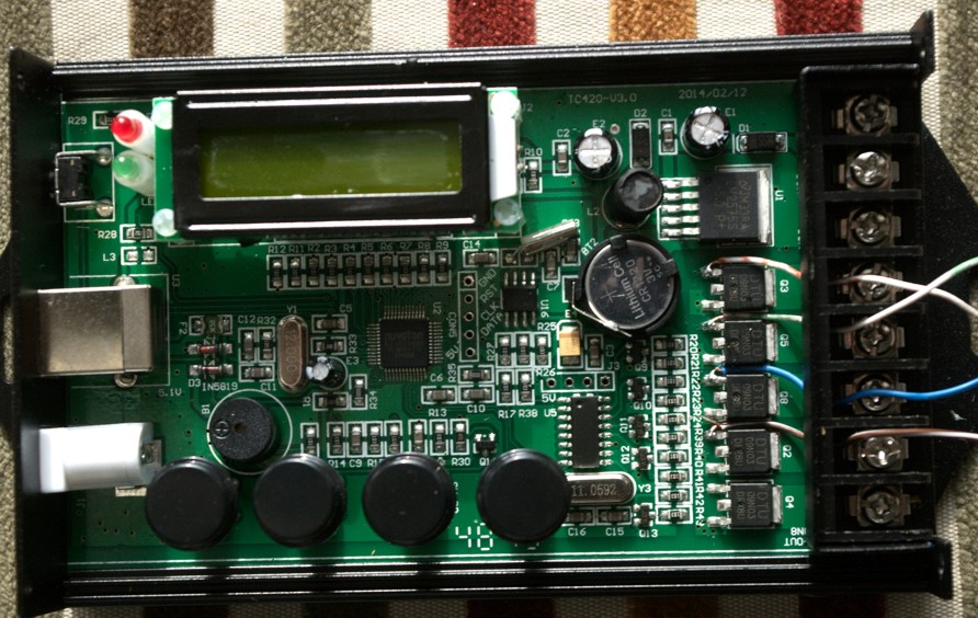
You can do the same for TC-420's if you want programmed control..
Note the new wire off the gate again..

tcmod1.jpg
 
Last edited:
Oreo, Thanks for your detailed reply. I am having a little trouble understanding everything here, please bare with me as my electrical skills are not up to par wih yours. Is your second photo a picture of the inside of the dimmer you linked?

Also, Is the white wire leaving the LDD soldered the the MOSFET?

What are the 2 9V power supplies for?


Thanks in advance

Second photo is the inside of the manual dimmer.
And yes the white (dim) wire is soldered to the gate of the internal MOSFET. Both the manual and TC-420 work the same way..you just don't use the "customary" output.
The manual dimmer (and TC-420) needs to be powered..
There specs state 12-24V but it has been found that other voltages will power it.. In the above case 9V. 5V doesn't work though..There is an internal voltage regulator that outputs 5V so technically the input voltage needs to be higher than output voltage (AFAICT). How many volts ???
9-24 DC seems fine and easy to get for cheap or free

The greater than 9V is just for the LEd's and LDD sake..
If your strings ran w/ 12-24V output the second power supply would be unnecessary (though you would need to watch your amperage of it)
If your diodes need more than 24V you need to as above to tie the power supplies neutral together..or that is how it worked for me.


Sounds confusing but it really is simple..

https://youtu.be/NcEA1gLPgdY
video only uses one power supply since the test string is under 12V

This shows a TC-420 running BOTH strip lights and an LDD off the same channel. One is direct cionnected normally, the LDD uses the "tap" off the MOSFET
https://youtu.be/1qm_5w7DDuA
 
Last edited:
Thanks oreo, People like you make projects like this easier to comprehend! Going to take some time to digest this
 
DISCLAIMER:
AFAICT the PWM frequency and voltage is LDD-H compatible..
Did this "trick" to 3 unrelated devices (Above 2 and a Mi-light Bluetooth unit)

If China decides to change things.. well not my fault.. ;)
 
OK, Recently received almost everything i need to finish my build. Still waiting on my TC420 controller. After assembly i have a few question hopefully someone an answer. I wired the LED channels directly into the cheap PWM dimmers linked above. I did this without tapping into the internal MOSFET and without taking the wire to the PWM input of the LDD drivers. The LED channels dimmed perfectly. Can someone please advice me if this is not wise to do? are there any problems i overlooked wiring it this way? I wired a dimmer With and without tapping into the MOSFET and noticed no difference. Thanks in advance!
 
OK, Recently received almost everything i need to finish my build. Still waiting on my TC420 controller. After assembly i have a few question hopefully someone an answer. I wired the LED channels directly into the cheap PWM dimmers linked above. I did this without tapping into the internal MOSFET and without taking the wire to the PWM input of the LDD drivers. The LED channels dimmed perfectly. Can someone please advice me if this is not wise to do? are there any problems i overlooked wiring it this way? I wired a dimmer With and without tapping into the MOSFET and noticed no difference. Thanks in advance!

Depends on the voltage of the power supply and current of the output..
Usually using the PWM "tap" off the dimmer is because the power supply exceeds the capacity of the internal MOSFET of the dimmer.
These are listed at 12-24 up to 5 or 6Amp (depends on the model) output I believe.

Overheating the MOSFET is a possibility..

BUT IF you are out of spec.. well who knows what will happen.
MOSFETS can only take soo much current/voltage for so long.

also there is an internal voltage regulator that drops the input voltage to 5V (I believe, or for sure close to this). That will now have to drop your power supply voltage to that level. If using larger than 24V that also will put a strain on the system. That chip can overheat as well..

What you are doing is just shifting the on/off full current line from using the LDD (their internal switch) to the MOSFET in the dimmer.
LDD are designed for larger loads than the dimmer..well sort of.. Larger voltages.

ONE other thing I just thought of.. You are now, basically turning the LDD off/on (rapidly). That may be a minor issue, as it needs to "adjust" its current each time.
 
Last edited:
Thanks again for your help oreo! Makes sense now. I will be using a 48v power supply. In the end i plan on using the TC420 you recommended. So my best bet will be tapping all 4 MOSFETs and wiring them into the PWM channels on the LDD's? Also, Am i correct that i no longer need to supply the inline 9v (+/-) voltage per your diagram when using the TC420 because it has its own power supply?
Using 48V, yes do the tap.
One of my tanks is running a 56V w/ a TC-420 but that power supply has a seperate 12V line which I use to power the TC-420.

Brings us to your next question.. Yes you need to power the TC-420.
some buy one of those cheap dc/dc voltage dropping boards off e bay and wire it from the power supply to the input of the TC-420..Avoids worrying about doing the common ground for 2 seperate power supplies.
IF I find the diagram I'll post it but basically you just tap off the power supply parallel to the power going to the LDD's and adj. the voltage down to 24V.
current draw will be minimal..

The 9V was what I used to test it.. also "out of spec" so to speak..but the TC was fine.
Any power supply from 9v to 24V will power it..(5V won't , verified by another).
 
Back
Top