Spectrometer modules for LED lighting analysis

theatrus

100-mile-commuter
Hi! You may remember me from other threads like LEDBrick DIY puck and high density stars, plus drivers and the Apogee sensor PAR interface board thread, and some other odds and ends.

Many moons (months) ago, I dropped some money into a GroupGets buy for a pair of Hamamatsu Micro-spectrometers.

1328733475697


They can resolve light intensity between 340-780nm in up to 15nm increments. They are not cheap ($180 on groupgets, qty1), but are a lot cheaper than other commercial pre-packaged light spectrum units that employ an actual spectrometer (and not a coarse approximation using an RGB light sensor). The actual absolute light intensity level is not specified (designed for relative or ratiometric measurements), so it likely wouldn't make a good PAR meter without a ton of calibration, assuming it had any repeatability of output.

They promptly sat on a shelf for awhile, until now.

The goal is to make a breakout/interface board for the units, USB and/or BLE (wireless!) and do some tests on LED lighting fixtures to see how it performs.

Stay tuned!
 
Last edited:
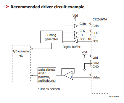
First things first, we need to figure out how to drive and read the spectrometer. There are two key diagrams to consult - the suggested application and the timing diagram.

app.png

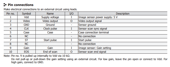
pins.png


The application diagram shows several key signals, some of which the meaning isn't clear at first. After reading through the rest of datasheet, you can generally make out the following pins:

* Video - the spectrometer is like a 2d camera - it is an image sensor in a line after all. Video represents the actual output, as an analog signal, of the sensor.
* Gain - an input, to select the gain
* CLK - A clock input
* ST - A start trigger
* EOS - an end of line/scan indicator - when this signal changes, you reached the end of the sensor

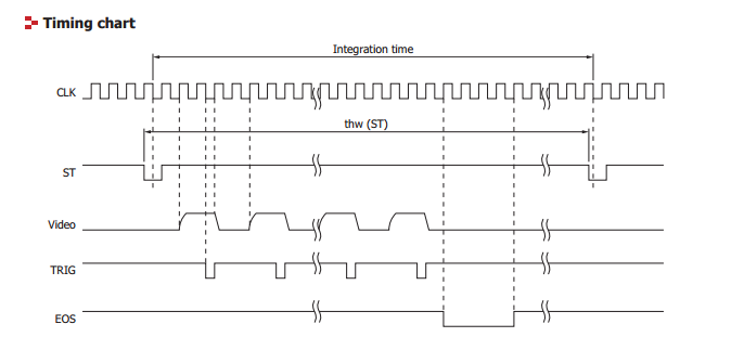
Now, the timing diagram:

timing_diagram.png

timing_diagram_notes.png


There are a few takeaways:

* The sensor needs a clock signal, of a fixed frequency. Based on the datasheet, it need not be very high (0.25 - 200kHz).
* The sensor has an integration time, that is, how long it is accumulating light in its internal cells before allowing them to be read out. This is the period between ST pulses, which means the sensor stores the light l\
evels into a buffer on readout.
* A new video pulse is available every 4 clock cycles. The video pulse is available by the second low clock transition.
* When the sensor is done, it drops EOS for 4 clock cycles.

So, what do we need to use this?

* An A/D. We need to be able to take the voltage from the VIDEO pin (from 0.15-3.3V) for every wavelength as we run the CLK pin. Ideally, this is a 14-16 bit A/D.
* A timing generator where we can produce a CLK rate, and a ST pin timer, at up to 800kHz. We also need to be able to read the A/D at 200kHz, synchronized with the above clock.
* A buffer op-amp - as the output of the sensor is very high impedance, and many types of A/Ds put a large load (relatively) on the signal, we need to provide a simple voltage follower.

In the next installment, I'll look at some interface potentials.
 
If you treat it like a "camera" CMOS readout (which is is very similar to) using such a large bit ADC is a bit unnecessary. Lots of noise in the lower bits.
12bit ADC is usually plenty..

You only need to read 256 (or so) pixels.
I do see their units use a 16bit ADC though.

http://www.hamamatsu.com/resources/pdf/ssd/mini-spectro_kacc0002e.pdf


Each pixel being relatively huge (12.5x1000um) means there is a lot of hope for a wide dynamic range. I'm not expecting top shelf Sony sensor performance here, but I'm hoping for at least 14 bits DR from it.

Using an on-MCU 12bit ADC reduces the part count and some complexity, but the on MCU units tend to be pretty compromised to an external ADC. Will investigate for sure :)
 
Considering what it "can do" and that currently any comparable product is $2000-ish dollars..def. worth following..

http://www.plastlist-group.com/led-8-1.php#link_3


http://www.probroadcastsupply.com/ikan-mk350-spectrometer-ikan-mk350/


Trick will be to get a fiber optic submersible wand coupled w/ it.. ;)


When it comes to optical engineering I'm fairly green. More to learn! :)

The cheapest unit I could find was a (reasonable?) $1400:

http://www.lightingpassport.com

It probably has this spectrometer in it ;)
 
When it comes to optical engineering I'm fairly green. More to learn! :)

The cheapest unit I could find was a (reasonable?) $1400:

http://www.lightingpassport.com

It probably has this spectrometer in it ;)
Or whatever is inside this, inside that.. ;) :
MK%20350%20spectrometer,%20luxmeter,%20spektrometre4.png


Lists a Toshiba CCD linear sensor though.. so not likely Hammamatsu
Pixel count is def. different:
Toshiba 1304DG linear CCD array
200 - 1100 nm
3648 pixels

http://www.cyttw.com.tw/english-pdf/dm-usb100-en.pdf

to be honest, and you may remember this, not too impressed w/ Ham. photodiodes..

might just want to trade the Ham for this.. Save you a pile of work...........;)
http://www.ebay.com/itm/USB-resolut...-F-/272214391997?_trksid=p2141725.m3641.l6368
 
Last edited:
Bigger and much finer resolution: http://www.cyttw.com.tw/english-pdf/dm-usb100-en.pdf - good find though.

Hamamatsu has some similar units. No idea on the cost - likely $1k++++ on their own. Once it's sold as lab equipment the sky is the limit on cost :)

I mean the physics of all of these are probably all pretty much the same: entrance port, slit, prism or diffraction grating, linear image sensor. The modular units would include the ADC.
Kind of fun to muck around in "luxury" stuff.. ;)
http://www.shop.spectrecology.com/S...-STS-VIS.htm?gclid=CNa1qczxz8wCFQyHaQodGiEDHg

;)
STS%20on%20Drone-960x720.jpg
 
Not a bad price at all there :)

The real question is how cheap can these micro units go in volume. Sadly I'm not likely to find out
 
Not a bad price at all there :)

The real question is how cheap can these micro units go in volume. Sadly I'm not likely to find out
Every one seems to have a different "heart".. ;)

That one above uses this sensor:
http://www.intins.co.kr/wp-content/uploads/ELIS1024.pdf

not sure why it is listed as a "Near IR " sensor though:
But:
Replaces entire CCD systems, not just the
sensor


http://www.dynamax-imaging.com/
http://www.dynamax-imaging.com/web/docs/products/Product_Selection_Guide.pdf
 
Last edited:
Quick update as I plan things out.

For the main microcontroller, I'm going for the successor to the Nordic nRF51 I used on my LEDBrick BLE controller, the nRF52832. Easy to make this portable on to a phone or tablet via Bluetooth LE.

http://infocenter.nordicsemi.com/in...r.nrf52/dita/nrf52/chips/nrf52832.html&cp=1_3

http://infocenter.nordicsemi.com/pdf/nRF52832_PS_v1.0.pdf

Bluetooth 4.2, Cortex-M4F (tasty FPU), 512KB of flash, 64KB of RAM, up to 64MHz.

The Bluetooth firmware blobs ("SoftDevices") are actually fairly straight forward to integrate with and the example applications work well.

In order to save some time and make any radio emissions concerns much easier when assembled, I'm going to use a pre-certified module, specifically the Rigado module which is ~$11 on DigiKey, and absolutely tiny:

https://www.rigado.com/product/bmd-300/

I'm also looking at putting it into a case, since the use mode is handheld after all.

This is nice, but quite huge compared to a phone.

http://www.polycase.com/vm-series

Also targeting this series of ADCs, available in a 14bit and 16bit pinout compatible version:

http://www.ti.com/product/ADC141S626
 
Taking a different tack with the enclosure and opting to just give up and use a Li-Poly pack.

I did some rough (rough!) modeling using http://www.polycase.com/kt-40 as the case, which easily fits the sensor and the LED array (for reflection/fluorescence measurement). The plan is to mount them to small right-angle carrier boards internally so they become end mounted.

There is enough clearance between the case and the board to fit an average small Li-Poly case (which are around 0.20"+ thick).

For power control, I'm planning on using the LTC3558 (http://www.linear.com/product/LTC3558) which offers charging, and two switching regulators in a tiny 0.4mm pitch QFN20. The first buck will feed the radio / main microcontroller, and the buck/boost will feed the 5V rail for the sensor, after passing through a high-PSRR low-dropout linear regulator to avoid feeding any noise from the boost converter back into the analog signal path (http://www.analog.com/en/products/power-management/linear-regulators/adm7170.html)
 
I finally got a few cycles to play with the devkit.

For example, here is a prototype AcroStrip with a 420nm violet, 3x Royal Blue, a mint and a 90CRI 5700k white, where the mint and white are driven at a lower point.

strip1.PNG


The sensors came from the factory tested to 11nm resolution through their entire range, which works out pretty well from this non-scientific reading of warm white fluorescents:

warm-fluorescent.PNG


The fluorescents produce a much spikier emission profile vs the LEDs from my testing so far.
 
Nice :)

Would be great to have something like this, but for me it would just be a toy and I couldn't justify the cost :(

Very interesting to read, but I'll have to stick with my seneye :(

Tim
 
You can build yourself a spectrometer verry cheap from an old webcam and by using a difracting grading from a compact disk.http://reefcentral.com/forums/showthread.php?t=2606060 I wanted to build one that had a light intensity sensor attached to the spectrometer and also a sensor for UV(UVB,UVC AND UVA).Also i wanted to make the spectrometer water resistant so i can measure the intesnsity and the blue and red under water then calibrate it with a par meter for the blue and red colors.It would be a tool that would measure a lot of the spectrum ,including UV and even infrared(webcams can see IR radiation).It would also measure PAR but the spectrometer would be more dvanced than any otther par meter on the market because you will know not only the PAR value but also how much blue compared to red there is in that par value asside from otther colors that the par meter does not even see.Then i would take pictures and make graphs with it,measuring spectrums.It can be done verry cheap.Because now i go without the reef aquarium and instead i have a coldwater tank that has verry litle light on it,i dont need such performant tool to measure light so i quit the idea of building the spectromter.
 
I finally got a few cycles to play with the devkit.

For example, here is a prototype AcroStrip with a 420nm violet, 3x Royal Blue, a mint and a 90CRI 5700k white, where the mint and white are driven at a lower point.

strip1.PNG


The sensors came from the factory tested to 11nm resolution through their entire range, which works out pretty well from this non-scientific reading of warm white fluorescents:

warm-fluorescent.PNG


The fluorescents produce a much spikier emission profile vs the LEDs from my testing so far.

Very neat. I made one of the webcam CD grating spectrometers , and it did work, but was not very precise. It was cool seeing the different peaks as I cycled through the channels of the LED that I was using at the time.

I would love to hear more about how you made out with this project.

Dennis
 
Back
Top