awais98
SPS
Hi everyone,
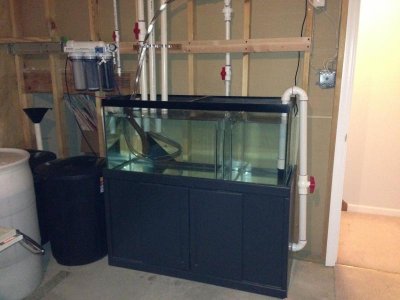
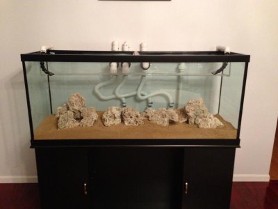
I'm a newbie and building this 120 gallon DT in the living room and a 70g Sump in the basement.
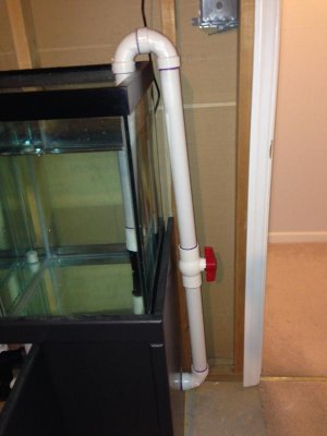
Ive done with most of the plumbing but I have a question that I am breaking my head with.
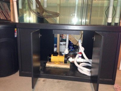
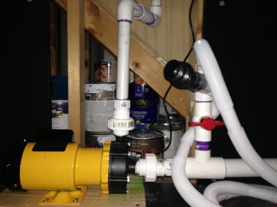
My return pump is an external panworld 200s and it is not self primed.
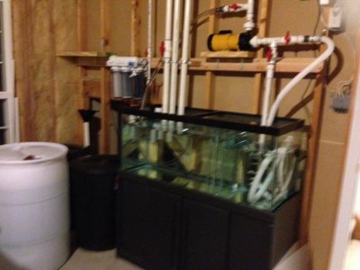
I have kept it above the sump ( see picture).
I do have additional hoses in the circuit at both the pump feed and pump out for priming and have put rubber check valve at both the pump feeds in the hope it will maintain the priming.
My question is, is this going to work fool proof if my electricity is ever down or Im in for some major trouble?
If it has to be changed then Ill have to re do a lot of plumping to keep the pump below the sump AND drill a hole in the sump for the gravity feed to pump.
Please help, what do you experienced folk think I should do?
Attaching the picture of my sump and the DT( DT background wall is in the making)
Thank you!
I'm a newbie and building this 120 gallon DT in the living room and a 70g Sump in the basement.
Ive done with most of the plumbing but I have a question that I am breaking my head with.
My return pump is an external panworld 200s and it is not self primed.
I have kept it above the sump ( see picture).
I do have additional hoses in the circuit at both the pump feed and pump out for priming and have put rubber check valve at both the pump feeds in the hope it will maintain the priming.
My question is, is this going to work fool proof if my electricity is ever down or Im in for some major trouble?
If it has to be changed then Ill have to re do a lot of plumping to keep the pump below the sump AND drill a hole in the sump for the gravity feed to pump.
Please help, what do you experienced folk think I should do?
Attaching the picture of my sump and the DT( DT background wall is in the making)
Thank you!
")
")