T5 retro kit wiring help!

migs671

New member
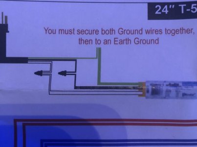
Hey guys just bought a retro kit and just a little confused of the wiring aspect of it specifically the grounding wire part

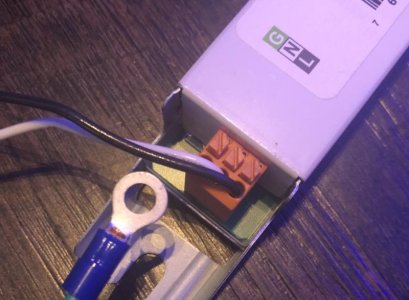
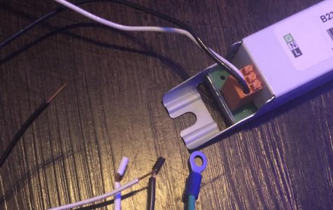
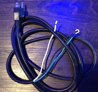
Where does the grounding wire get hooked up to

So was wondering if I can get some help here please

Also on a side note what can be used as a jumper wire replacement I lost the when that game with the box
 

Attachments

  • 60821DD6-7F2E-4C02-8234-1AFD93FA407D.jpg
    60821DD6-7F2E-4C02-8234-1AFD93FA407D.jpg
    36.3 KB · Views: 0
  • 808E49AB-5401-4CE4-AFA8-F31E5441D560.jpg
    808E49AB-5401-4CE4-AFA8-F31E5441D560.jpg
    56.6 KB · Views: 0
  • 6E26542A-5B10-445F-9A05-C28E9B34CBC5.jpg
    6E26542A-5B10-445F-9A05-C28E9B34CBC5.jpg
    65.3 KB · Views: 0
The ground wire gets tied to the 3rd ground pin on the plug..
You should be using a 3 conductor plug so you have line, neutral, and ground..
A 2 prong plug/cord is not sufficient unless you have some other method of grounding it
 
The ground wire gets tied to the 3rd ground pin on the plug..
You should be using a 3 conductor plug so you have line, neutral, and ground..
A 2 prong plug/cord is not sufficient unless you have some other method of grounding it

Thank you for the reply

So yes it does come with a 3 prob plug but I'm curious how do I connect the ground to the main cord coming from the prong

So it's 3 wires from plug and only 2 wires from ballast so trying to figure out how to hook up the ground
 

Attachments

  • EF925584-83B7-458E-A1CE-A5D7968C8D1A.jpg
    EF925584-83B7-458E-A1CE-A5D7968C8D1A.jpg
    97 KB · Views: 0
Well there is a spot for "g" on the ballast wire attachment block.
But like you see, they have a ring eye on the power cord..

Some ballasts that would just go to the screw that holds the ballast down. Grounding the case..

I should assume the ground point on the ballast wiring block should go to the case as well..

Guess you could use a VOM and see if you have continuity from case to the "G" header..

So the possible choices are
1)cut the ring off the end and attach the wire to the header per ballast diagram.
2)Just attach the ring to the screw that holds the ballast down
or
3)cover all bases and run a wire from the ballast to the screw and join it w/ the ring wire.
.
Pretty sure just cutting the eye off and stripping to attach to where its supposed to go should be the most logical one..

attachment.php


CUT..STRIP..ATTACH at "G"

Thank you bro for the help I'm going to do that
Was just kind of lost on what to do

Because on the sheet it says

"œMust secure both ground wires together then to an earth ground"
 
Go on YouTube and look up FishOfHex and find his retro fit kit video. It explains it and he talked about it all and shows how it's done.
I'm not very good at that stuff and I did it on the first try.

Sent from my SM-G892A using Tapatalk
 
Back
Top