Phixer
New member
super, because if you bond 2 surfaces directly together with WO40 such that they are a "perfect fit" the joint will push out the WO40 and you will end up with a dry joint.
If you read enough of this thread, you will see references to angles on the pieces to create the void. This I believe is the proper method. It is in this thread, you have to really search for it though. Try using the search function on this thread only for the term "40" or "42" and you might find it, also go back to the splits I think it's buried there.
Phixer, in reference to you question here is what James e-mailed me
Thanks Floyd...
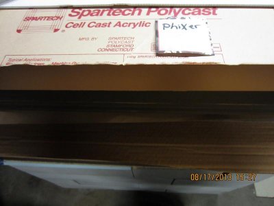
Forgot to mention to Supernemo earlier, the decision to use a CNC to mill these panels was recommended to me by the originator of this thread Steve Frosti aka Acrylicman many years ago when I talked to him on the phone. The other reason was because of the weight of handling these panels (500lbs ea) over a router table and the difficulty in doing this with a hand router was not something I was up to. In addition I wasnt sure if I I could replicate each edge as uniformly as a CNC could.
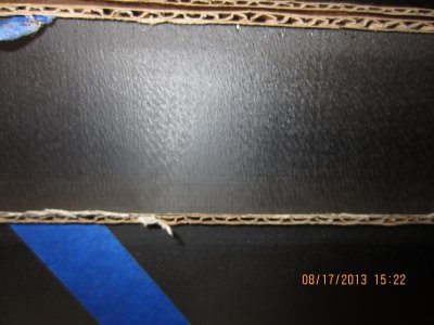
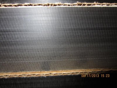
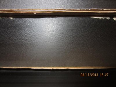
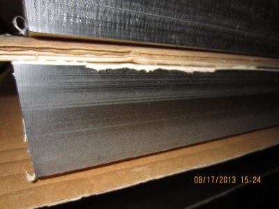
A CNC with a vacuum hold down table and laser sight was just a better option for me. The edges are good IMO but do have some minor lateral grooves in them. Probably due to feed rate as James mentioned. I hope they will be OK and not trap air. Upon closer inspection, the pitting is on the unmilled sides. Thank you for the reply and thank you James for your advice, it's always appreciated.
I plan on clamping a piece of 1/2 plate glass on the bottom of the V to keep the cement from running out.
Last edited:


")