You are using an out of date browser. It may not display this or other websites correctly.
You should upgrade or use an alternative browser.
You should upgrade or use an alternative browser.
(Another) DIY LED Build - Linear Design
- Thread starter katchupoy
- Start date
I ran my leds in 5 u channels single color more or less. so this....
CW-NW-CW-NW-CW-NW-CW-NW-CW-NW-CW-NW-CW
RB-RB-RB-RB-RB-RB-RB-RB-RB-RB-RB-RB-RB
So I have 3 blue runs and 2 white runs. The bars are spaced about 2 1/2 inches apart, the leds on each bar are 3 inches apart. It looks to have no color banding and the blend is very nice. I am not running optics though, as my light is 5 inches abouve my water.
vincent201089
New member
I just finish my demo an hour ago. "WHAO" is what I can say about led!
@katchupboy: I have a question on how to adjust the meanwell.
-I used the way on the reefledlights.com site and I set the driver at 780mA
-I retested it again by using your way with the 1ohm 2w resister and I only got 400-500mA.
I thought that I made some thing wrong so I went back to the way on reefledlights and what I read is 770-780mA.
When I turn the white screw in the driver, I notice that the screw can turn around more than 180 degree. In order to get 750mA, I only turn the screw a little bit, not more than 1/4 of 180 degree.
So... which one is correct? I'm thinking about using another way (the one on rapidleds.com)
katchupoy
New member
subscribed.awesome thread, katchupoy. and your username reminds me of a really funny actor here.

Yes you are correct... Thats him...
This is my way of saying hi and hello... kamusta kabayan!
Thank you for subscribing, may this thread help you in many ways.
katchupoy
New member
I ran my leds in 5 u channels single color more or less. so this....
CW-NW-CW-NW-CW-NW-CW-NW-CW-NW-CW-NW-CW
RB-RB-RB-RB-RB-RB-RB-RB-RB-RB-RB-RB-RB
So I have 3 blue runs and 2 white runs. The bars are spaced about 2 1/2 inches apart, the leds on each bar are 3 inches apart. It looks to have no color banding and the blend is very nice. I am not running optics though, as my light is 5 inches abouve my water.
Bam, thats good to know... in the future, try some optics... Or lower your light more. Congrats for no banding... do you like the color?
katchupoy
New member
I just finish my demo an hour ago. "WHAO" is what I can say about led!
@katchupboy: I have a question on how to adjust the meanwell.
-I used the way on the reefledlights.com site and I set the driver at 780mA
-I retested it again by using your way with the 1ohm 2w resister and I only got 400-500mA.
I thought that I made some thing wrong so I went back to the way on reefledlights and what I read is 770-780mA.
When I turn the white screw in the driver, I notice that the screw can turn around more than 180 degree. In order to get 750mA, I only turn the screw a little bit, not more than 1/4 of 180 degree.
So... which one is correct? I'm thinking about using another way (the one on rapidleds.com)
1) can you give us the link? is this the same link i have in the early part of this thread?
2) About the screw, Im not sure if they changed it so that now it will go beyond 180. Mine if I remember it right is somewhere 270 degrees or 3/4 turn.
3) Where do you put your test points? Also is the resistor inline? Did you just test both sides of the resistor?
4) did you also use/added a pot? Maybe this is the one screwing up your readings? It should be maxed out when testing?
I posted these before on another thread, but for katchupoy and encoure. Here is all whites (1000 mA) no blue full power.

Here is all lights full power the blues are at 700mA. There are 4 regular blues in the mix also. I think it looks slightly less blue in real life than in the photo.

I took an all blue photo and my camera made it look really psycodelic, so really not worth posting. Since I have nothing in my tank yet I am just running the leds at low power about 30% right now. You can see some mild bluer areas unser overhangs, but it is minimal and you have to be searching for it.
Here is all lights full power the blues are at 700mA. There are 4 regular blues in the mix also. I think it looks slightly less blue in real life than in the photo.
I took an all blue photo and my camera made it look really psycodelic, so really not worth posting. Since I have nothing in my tank yet I am just running the leds at low power about 30% right now. You can see some mild bluer areas unser overhangs, but it is minimal and you have to be searching for it.
Yes you are correct... Thats him...
This is my way of saying hi and hello... kamusta kabayan!
Thank you for subscribing, may this thread help you in many ways.
I always thinking you are the boy whom like ketchup.
vincent201089
New member
1. Yes, it's the link you gave us at the beginning. I followed this instruction:1) can you give us the link? is this the same link i have in the early part of this thread?
2) About the screw, Im not sure if they changed it so that now it will go beyond 180. Mine if I remember it right is somewhere 270 degrees or 3/4 turn.
3) Where do you put your test points? Also is the resistor inline? Did you just test both sides of the resistor?
4) did you also use/added a pot? Maybe this is the one screwing up your readings? It should be maxed out when testing?
- Use a 3-12v power supply.
- + output from power supply to dim+, - output to dim-
- turn the meter reader to 10A, red at 10A, black at common
- the red connect to V+ on driver and the black connect to V+ on led
- V- on driver connect to V- on led
- put everything inline and started to turn everything on.
- I realize that I got the same mA at 3v and 9v like in the video, but I can't see how much he turn the screw.
2. I didn't adjust the driver for XP-G cool white. The driver is 1.3A and the XP-G is 15A max. But when I follow the instruction 1, I only turn the screw just a bit. I mean even I just move the screw driver, the # change immediately. I feel that the blue isn't bright although it was set at 750mA
3. I put the resister (1ohm 2w at fry's) in line between the led+ output from driver and led+ input from the led fixture. Yes, I tested both side and only got 480-500mA.
4. The only thing I use is meter reader, wire from the kit, led lights and resister, the power supply I used to make 10V signal is the one for my moonlight 3v-12v and I set mine at 9v. That's it.
There's another way that on the rapidled's site.
- Use a dim and connect to dim+,- and set it at max 10v
- set the meter at 10A, red at 10A and black at common.
- break one cord between 1 pair of led
- put and hold the black and red to that point +,- on the led light.
- turn on and start to adjust the screw.
vincent201089
New member
I just finished the third way and I got
-650mA on the blue led which I got 480-500mA and 750mA at the same setting.
-on the white led I got 1.9A at max setting. The driver only can provide 1.3 Max, now I got 1.9A.
I don't know what to do, which one should I trust?
Is there any other way I can use to read mA?
-650mA on the blue led which I got 480-500mA and 750mA at the same setting.
-on the white led I got 1.9A at max setting. The driver only can provide 1.3 Max, now I got 1.9A.
I don't know what to do, which one should I trust?
Is there any other way I can use to read mA?
katchupoy
New member
I just finished the third way and I got
-650mA on the blue led which I got 480-500mA and 750mA at the same setting.
-on the white led I got 1.9A at max setting. The driver only can provide 1.3 Max, now I got 1.9A.
I don't know what to do, which one should I trust?
Is there any other way I can use to read mA?
vincent... everything looks ok except...
when you did the test without the resistor... your meter is set to amps.
but when you do the inline with resistor. I did not see on your post if you changed your meter to "volts" ???? maybe I read it too fast... i will go back again and re read... nope i did not see it... so maybe this is the key... please set you meter to volts... your reading here should be millivolts or volts...
let me know.
Last edited:
katchupoy
New member
There's another way that on the rapidled's site.
- Use a dim and connect to dim+,- and set it at max 10v
- set the meter at 10A, red at 10A and black at common.
- break one cord between 1 pair of led
- put and hold the black and red to that point +,- on the led light.
- turn on and start to adjust the screw.
Am i too late?
Please be extra extra careful when breaking the connection on the LED... make sure that you
turn the whole system off first
break the line
put the meter
then turn it on
then
turn it off,
remove the meter
reconnect the line
then turn it on...
katchupoy
New member
I always thinking you are the boy whom like ketchup.
your almost correct... ketchup against katchup... the e and a...
and i dont like ketchup.. that is so weird.
King Nikon
New member
I got a couple questions about LEDs. It's kinda long but hopefully someone will help me out.
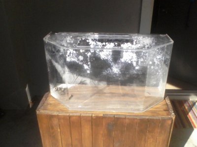
First off my tank I'm setting up is a 30 gallon acrylic, it's measurements are 30 1/2" x 13" x 16". I uploaded a picture at the bottom for some reference.
I want this tank to be very blue to simulate a deep ocean environment for it's inhabitant so I was thinking all Royal Blue. The issue is the lighting needs to be no more than the power of 2 T5's (48 watts) but preferably somewhere between 1 (24 watts) to 1 1/2 (36 watts).
So if I get 12 Royal Blue XP-E mounted about 12" - 18" high with some 60° lenses, is this approximately what I need or is it too much? I want to be able to have low light mushrooms and maybe a low light softy in there.
If you're wondering why it needs to be so specific is because the inhabitant is going to be a Peacock Mantis Shrimp and too much lighting causes shell rot, which can be fatal.
Attachments
TheFishMan65
New member
Didn't i answer this somewhere else? About 3 watts of T5 is the same as one watt of LEDs. So 16 LEDs would probably be good. If you get a dimmable driver you can turn it down.
[EDIT]
This is what I read - sorry no way to verify it.
[EDIT]
This is what I read - sorry no way to verify it.
katchupoy
New member
I got a couple questions about LEDs. It's kinda long but hopefully someone will help me out.
First off my tank I'm setting up is a 30 gallon acrylic, it's measurements are 30 1/2" x 13" x 16". I uploaded a picture at the bottom for some reference.
I want this tank to be very blue to simulate a deep ocean environment for it's inhabitant so I was thinking all Royal Blue. The issue is the lighting needs to be no more than the power of 2 T5's (48 watts) but preferably somewhere between 1 (24 watts) to 1 1/2 (36 watts).
So if I get 12 Royal Blue XP-E mounted about 12" - 18" high with some 60° lenses, is this approximately what I need or is it too much? I want to be able to have low light mushrooms and maybe a low light softy in there.
If you're wondering why it needs to be so specific is because the inhabitant is going to be a Peacock Mantis Shrimp and too much lighting causes shell rot, which can be fatal.
I believe you are good, but i would try to put 2 whites in there without optics.
the blue alone is similar to black light so you might not like it... you only see corals that fluoresce... so adding 2 CWs will should work..
B B W B B B B B B W B B
And get the dimmable "48D" so you can fine tune how low is your low...
vincent201089
New member
No I didn't set my meter to volts, I put it at 10A because I'm O with this. I'll try it later.Am i too late?
Please be extra extra careful when breaking the connection on the LED... make sure that you
turn the whole system off first
break the line
put the meter
then turn it on
then
turn it off,
remove the meter
reconnect the line
then turn it on...
What is the volts option you are talking? Sorry for the flash light
Is it plug the red into V ohm mA (the one in the between 10A and common) and turn the knob to 2000m on the high left corner?
I got 650mA on the blue and 1200mA on the white.

I read many posts and I always follow the instruction that turn off power, break, connect to meter and turn on, or turn off power, re-connect and turn on.
BTW, while we're using the leds, if one of the cord is disconnect by accident or something, will it damage the whole unit when the light schedule on again?
Last edited:
katchupoy
New member
the V on the upper left.. maybe set it to 20 if the reading is too big then you can try 2000m and then 200m
IT IS MY FAULT!!!
I cant believe I did not mention this on my tutorial!!! WOW, I misssed it somehow...
When testing amps on an inline resistor, we need to change our meter settings to "VOLTS". Im so sorry...

IT IS MY FAULT!!!
I cant believe I did not mention this on my tutorial!!! WOW, I misssed it somehow...
When testing amps on an inline resistor, we need to change our meter settings to "VOLTS". Im so sorry...
Last edited:
vincent201089
New member
No, not yours. If I look closer to the pic on the first page. I could see the way you set your meter.
I set mine at 2000m and got 650. Did you try another way and still got the same reading?
I set mine at 2000m and got 650. Did you try another way and still got the same reading?
Similar threads
- Replies
- 14
- Views
- 2K
- Replies
- 2
- Views
- 2K
- Replies
- 16
- Views
- 2K