You are using an out of date browser. It may not display this or other websites correctly.
You should upgrade or use an alternative browser.
You should upgrade or use an alternative browser.
Auto top off not working
- Thread starter Johnb123
- Start date
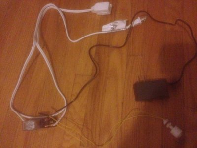
My only guess is I connected the wrong side of the live wire however it was the smooth side of the extension cord that I cut. Before I cut the otherside of the extension cord is there something else I could have connected wrong on the relay? Thanks.
Attachments
outy
New member
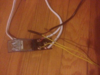
i just cut the other side and still doesn't work there's something wrong with the wiring
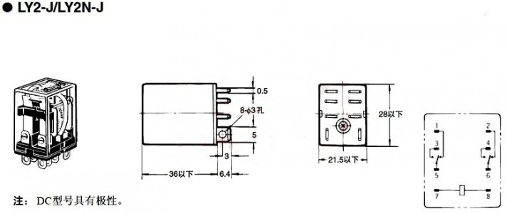
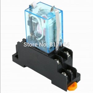
this is the diagram of my relay if someone can tell me how to wire it thanks
I own the same one.
Take all leads of relay switch
If you disconnect the float, the 12v power leads should trigger the relay, you can hear and see it.
If that's not working either the relay is bad or you don't have 12v
outy
New member
a broken relay? ..
Yes.
If you are giving the top two connectors 12V and the solenoid is not clicking then it is broken.
orange thing is to connect it onto a piece of din rail. You need a 12v coil that looks to be 120 or 240v coil maybe? 7 & 8 are your coil terminals. One side of you power supply would go on one of them. Then one side of your float switch would go on the other. Then splice the other side of the power supply to the other side of the float switch. That will turn relay on and off as required.
outy
New member
mines a 12v. so my power supply and float go on terminals 7 and 8? what number terminals does my extension cord attach to?
Don't listen to him.
use the lower ones like you had.
Ive had mine for almost ten years and just replaced floats yesterday and rewired up mine.
Also removed one float and had it wired identical to yours in your pics above.
You had it wired correctly, its just a bad relay, they are cheap replace it
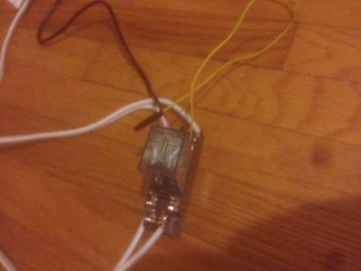
thanks page it works! however i connected 2 float switches now how come they don't work independently? i want to make it so if a snail is holding down the first switch then if the water rises to the next switch it turns off but they seem to only work together and only turn off when both switches are lifted. flipping the floats around didn't help either.
i have it hooked up in series. i want it so that it turns off when either switch is lifted. so if there's a snail holding down the first switch then the second switch can turn off alone once water gets to it.
i just switched the float switch wires to test if it's a negative/positive issue but nothing changed. does the way float switches are connected in series matter which pos and neg are connected together? it ends up being the same for me but i don't want issues down the road
i just switched the float switch wires to test if it's a negative/positive issue but nothing changed. does the way float switches are connected in series matter which pos and neg are connected together? it ends up being the same for me but i don't want issues down the road
Similar threads
- Replies
- 4
- Views
- 2K
- Replies
- 11
- Views
- 207