Disabling photo transistors?

Ermin

New member
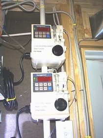
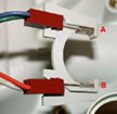
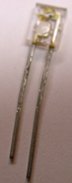
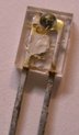
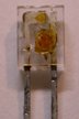
I want to disable the "drip sensors" on my perisaltic feeder pump. After opening the pump unit, I found two sensors located close to where the drip capsule is at. I'm guessing they are photo transistors(?). The sensors face each other with the drip capsule in the middle. The sesors notify the unit if there are actual liquid passing through. Each sensor has two legs. One longer than the other, I'm assuming its like cathode and anode ends on LEDs. Each leg has a wire connected to it...so there are a total of 4 wires. The four wires then connect to the main electronic circuit board.

I don't know if there is an easy way to bypass the sensors (ie. close each pair of wires with resistor?).

Any help is greatly appreciated.
 
Ermin,

I have to crash tonight. burnt out. But I will get to this as fast as I can. probably saturday. if someone else doesn't grab it.

too tired to think electronics right now.
 
Labels "A" and "B" are the locations where the photo diode sensors are at. The curved center is where the drip capsule sits. Two wires connect to each diode (is that what the part is?) via a brown connector.
 
Sorry for the small image. The board limits the attachment size.
 

Attachments

  • sensor.jpg
    sensor.jpg
    49.1 KB · Views: 0
If you want it to always think there is water passing by it, this could be as simple as putting a drop of silicon on it.
 
mmhhh!!!
I'll tag along

I also have a doser, and tried to bypass the sensor in many ways, but no luck.
The silicon drop option sounds interesting, I'll try it.
 
I was going to suggest the same thing. Depending upon how the circuit works, it could be as easy as covering one side with something that light can't pass through.

ie. if the circuit only works when the light is blocked then cover one or both sensors. If it only works when the light is passed then remove the sensors from their mount and tape them up right up next to eachother.
 
I think Pyro has nailed it. You could certainly figure out how to cut/bypass them, but just taping them together (or apart) should do what you need, and leave it in a state where it can be easily put back if needed.

Zeph
 
Unless of course it is actually a drip sensor and needs the on off action rather than a constant on or off action.

Kim
 
I'll try taping one side and see if it will work....

I've already tried and didn't work:
1.) Removed the sensors and had them face each other and taped together. (maybe the sensors need to "see" the chopping of lighting as droplets pass through)
2.) Bridging the legs on each sensor, thus completing the circuit.

The sensor requires constant on/off signal. When no liquid is sensed, the pump stops and displays "flow error". When liquid is not passing through in predetermined drops, (ie. several drops at once), the pump stops and displays "free flow".
 
Hey,

ok what you have done by blocking the sensors is to tell the microprocessor that there is a steady stream of water passing by. which it doesn't want. It is looking for a specific rate of drips. More specifically it is looking for edge changes in the signal coming out of the pump. What it does is it tries to match the drip rate(and therefore signal changes) to a set pule rate(frequency) inside the processor. ie one per second.

Why do you want to disable it? the flow rate sensors that is?

Without playing with the pump I'd say what you will need to do is either disable the drip counting circuitry or need for that circuitry.

To do this you will either need to take the drip rate timing signal and feed it back into where the sensor signal is sent into the processor. Or else disable that portion of the circuitry that the processor thinks it has to think it needs a correct pulse to send the signal to let more water flow.

I have other ideas but I'd need to mess around with the pumps control circuitry. with a scope n such.
 
What type of pump do you have? If itââ"šÂ¬Ã¢"žÂ¢s a kangaroo 324 I know how to disable the sensor, on the 324 it is as simple as soldering a jumper wire between two legs of the firmware chip, I have three of these pumps and it has worked on all of them.
 
Darren, When the drip capsule that sit between the photo sensors (works like a bubble counter, but this is empty and counts drops of liquid instead of CO2) is cloudy or dirty, the pump stops. Its a safety mechanism for the pump since it was designed for medical use. For my purpose of feeding my nilsen reactor, it doesn't matter if its dripping or not. I check it daily anyways. Every single occurance of reported error from the pump had been false alarms. Everything is always working.... somehow it is just the sensors thinking it is not. So, I just want to disable it, to rid the troubles.

Greeneyedblackcat, I have two pumps. One was bought many years ago from Innovative Aquatics. Sine they put their label on it...I'm not sure....but it looks 99% like a Kangaroo though....so I would guess the circuit is the same. If you can tell me more on how u disabled it, that'll be great!

The other pump is a COMPAT feeding pump, made by Novartis Nutrition. That's the one I'm tweeting with right now. But ultimately, I want to fix both.

Also, where do you buy your replacement tubing for the Kangaroo?
 
Ahh good reason to get rid of the sensors.

I have a feeling what you will need to do is disable it as GEBC has said he knows how to do. It's not just a matter of cutting or taping sadle enough.

The saftey features are there and aren't easy to bypass. Well to most. :)

good luck with it.

GEBC,

can you post diagrams of what is needed to be done? For otehrs in the future? A sketch woudl be enough. Then I can sit down and make a schematic.
 
Kangaroo

Kangaroo

Ermin, Here is a picture of kangaroo 324 pumps, I will take mine apart tonight and get you a picture of the modification, you feed the signal back where it came from on the firmware chip via a jumper soldered in, as to the pump dripsets I get them off ebay, the standard dripset only flows about 2 gallons a day without any head pressure, with head pressure you get even less. I do have one kangaroo that I modified the dripset, I installed a piece of 3/16ââ"šÂ¬Ã‚ peristaltic tubing in place of the Standard dripset, and the volume has tripled to 900ml per hour, I use it to feed my Diy calcium reactor>>>>>>>>>GEBC
 

Attachments

  • kangaroo 324s.jpg
    kangaroo 324s.jpg
    40.6 KB · Views: 0
Back
Top