Daimyo68
Active member
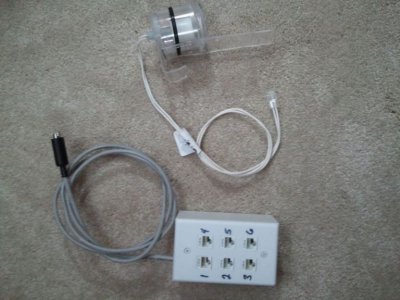
I've seen lots of pictures, both inside and out, of DIY Breakout Boxes for the Neptune Apex, but no "how to", so I thought I would write this up for those interested. I built mine with all 6 inputs on 1 side of the project box. This leaves me room to expand at a later date, without having to screw another item/box to the stand.
I've included images, some not that clear (crappy cell camera). Read through the project and make sure you know whats involved if you are unsure you can do it. (If I've missed anything, I'll PM a Moderator for an edit).
It's pretty straight forward and simple, but no reason to get burned by the soldering iron, or make a mistake when soldering the colored wires.
Parts Needed:
1 Project Box - http://www.radioshack.com/product/index.jsp?productId=2062280
2 x 1/8" Mono Panel-Mount Audio Jack (3 per pack) - http://www.radioshack.com/product/index.jsp?productId=2103453
20 Gauge Wire - (This is more wire then you will ever need. Ask your friends or neighbors, I'm sure they have some laying around, and you only need 6" for this build) - http://www.radioshack.com/product/index.jsp?productId=2049743
8 Pin MiniDin Cable - http://www.amazon.com/Belkin-Din8M-Serial-Printer-Cable/dp/B00004Z59N
1 small Zip-Tie
When it comes time to add float switches or another type of open/closed circuit, you can wire/solder them to these:
1/8" Shielded Cable - http://www.radioshack.com/product/index.jsp?productId=2103854
Tools Needed:
Drill
1/4" Drill Bit
Dremel or Razor Blade
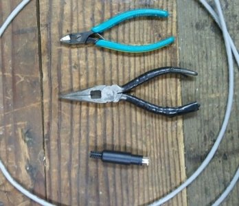
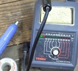
Low Wattage Pencil Tip Soldering Gun (you don't need a blowtorch here! A low wattage gun will work fine, and the pencil tip is more precise)
Solder (I used Electronics Solder)
Sandpaper (optional if needed)
Liquid Black Tape (Not needed, but it makes me feel better)
Extra's
Six Pack of beer (or your favorite whiskey)
Your favorite music or a game playing in the background on the radio
When you first open the Project Box, you will notice that it has 3 "slots" on each side. These slots need to be removed. This can be done with a Dremel, or a razor blade (carefully, don't need to go to the hospital, you have a breakout box to build). Once you get the bulk of the slots out, sand it down smooth with the sandpaper or Dremel.


Once you've got the slots taken down, you can now drill your 6 holes for the Audio Jacks. Make sure to leave enough room between each hole for wiring later. If you want to get precise with the spacing, I spaced mine 9/16" from center to center on each hole. This leaves enough room for wiring while being at the max that you can be inside the box without hitting the screw towers. (I didn't smooth out all the slots at this point, but you get the idea). Now would also be a good time to drill a hole on one end for the cable to go through. Drill the hole to the right side of the box (looking at the next image) so that you follow along with what I did.

You can put in the audio jacks to make sure they fit, but they will need to come back out to do some soldering of the ground circuit. Look at it, it's clean looking.
Mental Note Here***
The jacks are numbered 1-6, starting at the left in the following image. And your hole for your cable should be on the left side now. Remember this, you will need it later.

Ok, so as mentioned, the next step is to solder our ground circuit. All 6 inputs use a common ground circuit, so what we are going to do here is to create a "bridge" from the first jack to the 6th. To do this, mount all 6 audio jacks from the outside in. Yes, mount them backwards. This will make soldering them easy. (The following image is my sad attempt to show you the general idea, since I forgot to take pics of this step, I had to photoshop the jacks in there)

On the jack, there are 2 "ears". Each one is a separate circuit on the jack. To make things easy for the ground circuit, what I did was line up the ears in a horizontal position. Once they are pretty straight, cut a piece of 20gauge wire, 7" long. Strip 3" of the plastic sleeve off one end and loosely twist the wire, creating a "cable". You will be laying this cable across all 6 ears, hence making a bridge sort of say for the ground circuit of your DIY Breakout Box.
Plug in your Soldering Iron and let it heat up. While your waiting, lets have a look at what we are going to solder the wire to. In the 1st image below, I have the Red Arrows pointing to the "ears" that you will lay your wire across. In the 2nd image, I have a Green Line representing where the wire/cable should be laying and soldered to when finished with this step.
So now your soldering gun is warmed up, go ahead and solder your "bridge" together, leaving the plastic sleeve on the one end of the wire.


Ok, pop open that first beer and let things cool down.
Now that the ground circuit is soldered to the jacks, remove them all and put them in correctly. The "Bridge" should be at the bottom of the box, not facing up. This keeps it out of the way. They should fit perfectly into the holes if you measurements were dead on. If not, a little "umphff" will get them in there. Secure them from the outside with the provided nuts and lock them down. They won't be coming back out. This is where I used the Liquid Black Tape. "Paint" it onto the "bridge". It's not necessary being that the ground is at the bottom of the box, but it's added insurance.
Set the box to the side and grab your 8 pin MiniDin cable. Cut it to your desired length. (I bought a 10' cable Belking Cable from Staples, and cut it in half). Strip back a few inches of the outer sheath, exposing the wires. If your using the Belkin Cable that I linked to, then you use the following colored wires. I've also listed below which circuit/input they correspond to on the APEX. If your not using the Belkin Cable, then you will need to figure out the color/pin on your own.
Red - Pin 1 - Input #1
Brown - Pin 2 - Input #2
Green - Pin 3 - Input #3
Yellow - Pin 4 - Input #4
Orange - Pin 5 - Input #5
Grey - Pin 6 - Input #6
Purple - not used
Blue - Pin 8 - Ground
Ok, remember that hole that you drilled on the one end of the box? Put your cable through it, and leave it loose at this point so you have some slack to play with. This is the toughest part of the project. You will need to solder each wire to its corresponding jack. Remember earlier, I mentioned the "Mental Note"? Ok scroll back up and and read it then come back here.
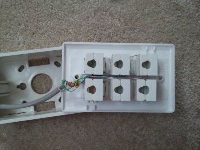
Using the Wire Colors listed above, start at Jack 1 and solder the Red wire to the 2nd ear on the jack, then the brown to jack 2, etc etc. The last wire to solder will be your Blue wire. Solder it to the wire that was left hanging from your "bridge". I mentioned this is the toughest part. This is because if your not steady with the soldering iron, you will melt plastic in the box (As can be seen in the following images...Yeah I finished the 6pack before I got to this step).
Another alternative to this possible problem, would be to solder the colored wired to their respective jacks before putting the jacks into the box. (ha ha were putting Jack in the Box... get it? Jack in the Box? ok I thought it was funny) If your doing it this way, just make sure you have everything laid out properly, and that your cable goes through the box before soldering.
Once done soldering, pull your slack cable back out until almost at the end, grab that Zip-Tie and secure it on the inside of the box.
Either way, when your done, you should now have a box that looks like this:

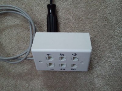
Grab the 4 screws, put the cover on and your done. Here's the completed box:

This DIY Breakout Box works exactly the same as the one from Neptune. They make a great product, and theirs can be had at many online retailers. I just wanted to make one myself.
Now go grab another 6pack and get that DIY ATO put together!
Enjoy,
/D
I've included images, some not that clear (crappy cell camera). Read through the project and make sure you know whats involved if you are unsure you can do it. (If I've missed anything, I'll PM a Moderator for an edit).
It's pretty straight forward and simple, but no reason to get burned by the soldering iron, or make a mistake when soldering the colored wires.
Parts Needed:
1 Project Box - http://www.radioshack.com/product/index.jsp?productId=2062280
2 x 1/8" Mono Panel-Mount Audio Jack (3 per pack) - http://www.radioshack.com/product/index.jsp?productId=2103453
20 Gauge Wire - (This is more wire then you will ever need. Ask your friends or neighbors, I'm sure they have some laying around, and you only need 6" for this build) - http://www.radioshack.com/product/index.jsp?productId=2049743
8 Pin MiniDin Cable - http://www.amazon.com/Belkin-Din8M-Serial-Printer-Cable/dp/B00004Z59N
1 small Zip-Tie
When it comes time to add float switches or another type of open/closed circuit, you can wire/solder them to these:
1/8" Shielded Cable - http://www.radioshack.com/product/index.jsp?productId=2103854
Tools Needed:
Drill
1/4" Drill Bit
Dremel or Razor Blade
Low Wattage Pencil Tip Soldering Gun (you don't need a blowtorch here! A low wattage gun will work fine, and the pencil tip is more precise)
Solder (I used Electronics Solder)
Sandpaper (optional if needed)
Liquid Black Tape (Not needed, but it makes me feel better)
Extra's
Six Pack of beer (or your favorite whiskey)
Your favorite music or a game playing in the background on the radio
When you first open the Project Box, you will notice that it has 3 "slots" on each side. These slots need to be removed. This can be done with a Dremel, or a razor blade (carefully, don't need to go to the hospital, you have a breakout box to build). Once you get the bulk of the slots out, sand it down smooth with the sandpaper or Dremel.


Once you've got the slots taken down, you can now drill your 6 holes for the Audio Jacks. Make sure to leave enough room between each hole for wiring later. If you want to get precise with the spacing, I spaced mine 9/16" from center to center on each hole. This leaves enough room for wiring while being at the max that you can be inside the box without hitting the screw towers. (I didn't smooth out all the slots at this point, but you get the idea). Now would also be a good time to drill a hole on one end for the cable to go through. Drill the hole to the right side of the box (looking at the next image) so that you follow along with what I did.

You can put in the audio jacks to make sure they fit, but they will need to come back out to do some soldering of the ground circuit. Look at it, it's clean looking.
Mental Note Here***
The jacks are numbered 1-6, starting at the left in the following image. And your hole for your cable should be on the left side now. Remember this, you will need it later.

Ok, so as mentioned, the next step is to solder our ground circuit. All 6 inputs use a common ground circuit, so what we are going to do here is to create a "bridge" from the first jack to the 6th. To do this, mount all 6 audio jacks from the outside in. Yes, mount them backwards. This will make soldering them easy. (The following image is my sad attempt to show you the general idea, since I forgot to take pics of this step, I had to photoshop the jacks in there)

On the jack, there are 2 "ears". Each one is a separate circuit on the jack. To make things easy for the ground circuit, what I did was line up the ears in a horizontal position. Once they are pretty straight, cut a piece of 20gauge wire, 7" long. Strip 3" of the plastic sleeve off one end and loosely twist the wire, creating a "cable". You will be laying this cable across all 6 ears, hence making a bridge sort of say for the ground circuit of your DIY Breakout Box.
Plug in your Soldering Iron and let it heat up. While your waiting, lets have a look at what we are going to solder the wire to. In the 1st image below, I have the Red Arrows pointing to the "ears" that you will lay your wire across. In the 2nd image, I have a Green Line representing where the wire/cable should be laying and soldered to when finished with this step.
So now your soldering gun is warmed up, go ahead and solder your "bridge" together, leaving the plastic sleeve on the one end of the wire.


Ok, pop open that first beer and let things cool down.
Now that the ground circuit is soldered to the jacks, remove them all and put them in correctly. The "Bridge" should be at the bottom of the box, not facing up. This keeps it out of the way. They should fit perfectly into the holes if you measurements were dead on. If not, a little "umphff" will get them in there. Secure them from the outside with the provided nuts and lock them down. They won't be coming back out. This is where I used the Liquid Black Tape. "Paint" it onto the "bridge". It's not necessary being that the ground is at the bottom of the box, but it's added insurance.
Set the box to the side and grab your 8 pin MiniDin cable. Cut it to your desired length. (I bought a 10' cable Belking Cable from Staples, and cut it in half). Strip back a few inches of the outer sheath, exposing the wires. If your using the Belkin Cable that I linked to, then you use the following colored wires. I've also listed below which circuit/input they correspond to on the APEX. If your not using the Belkin Cable, then you will need to figure out the color/pin on your own.
Red - Pin 1 - Input #1
Brown - Pin 2 - Input #2
Green - Pin 3 - Input #3
Yellow - Pin 4 - Input #4
Orange - Pin 5 - Input #5
Grey - Pin 6 - Input #6
Purple - not used
Blue - Pin 8 - Ground
Ok, remember that hole that you drilled on the one end of the box? Put your cable through it, and leave it loose at this point so you have some slack to play with. This is the toughest part of the project. You will need to solder each wire to its corresponding jack. Remember earlier, I mentioned the "Mental Note"? Ok scroll back up and and read it then come back here.
Using the Wire Colors listed above, start at Jack 1 and solder the Red wire to the 2nd ear on the jack, then the brown to jack 2, etc etc. The last wire to solder will be your Blue wire. Solder it to the wire that was left hanging from your "bridge". I mentioned this is the toughest part. This is because if your not steady with the soldering iron, you will melt plastic in the box (As can be seen in the following images...Yeah I finished the 6pack before I got to this step).
Another alternative to this possible problem, would be to solder the colored wired to their respective jacks before putting the jacks into the box. (ha ha were putting Jack in the Box... get it? Jack in the Box? ok I thought it was funny) If your doing it this way, just make sure you have everything laid out properly, and that your cable goes through the box before soldering.
Once done soldering, pull your slack cable back out until almost at the end, grab that Zip-Tie and secure it on the inside of the box.
Either way, when your done, you should now have a box that looks like this:

Grab the 4 screws, put the cover on and your done. Here's the completed box:

This DIY Breakout Box works exactly the same as the one from Neptune. They make a great product, and theirs can be had at many online retailers. I just wanted to make one myself.
Now go grab another 6pack and get that DIY ATO put together!
Enjoy,
/D
Last edited:


