DIY Apex Breakout Box Instructions/Parts List

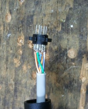
Next strip the cat5e cable and measure to ensure the gray sheilding will still be witihn the completed mini-din.

Then color code can be your choice. An industry standard for telecom is;
blue, bl/w, green, g/w, orange, o/w, brown, br/w.

As the Apex only uses 7 pins I cut the brown/white wire off. Then strip an ever so small amount of the shielding from each wire.
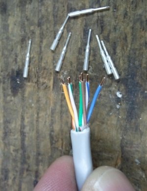
2011-01-05 21.18.50.jpg

Your ready to solder, just be careful not to leave and solder buggers on the pins as they may short out once assembeled in the slug.
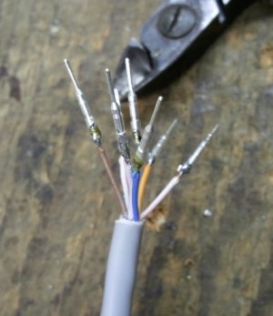
2011-01-05 21.23.43.jpg
 
Finally you are ready for assembly.

Using the color code of your choice, align and insert all of the pins into the slug according to the Apex new user guide page 84.

Once the pins are inserted, using the needle nose slowly and carefully seat each pin a little. Then make a second seating round and firmly seat each pin.

2011-01-05 21.33.21.jpg

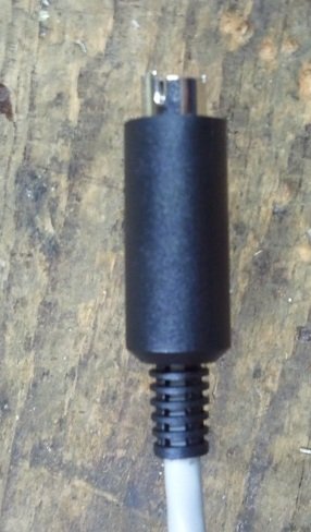
Once done just reassemble the connector housing and slide the outer mini-din casing over the barrel.

2011-01-05 21.34.20.jpg

Your done.

A note: once the outer connector housing is slide over the barrel it is difficult to remove, you may want to check for shorts between pins before assembly.
 
jrpark thanks for photos, just what i needed to see, I couldn't visualize the connector. Picture is worth at least a thousand words at times.
I too really appreciate the folks that do step by step instructions with photos and mention any issues that can make it easier for us to decide whether to undertake various projects. Sometimes we jump in and realize its not that easy for us and then have to buy instead. frustrating it can be..
So far I have only DIYed 2 items, PVC skimmer, and a small sump, and working on my pvc overflow. All ideas from this forum. Thanks again folks.
 
I built one, though I may have screwed something up. Doesn't seem to work for me :)

I need to find some time to troubleshoot it.. been too busy with a house/addition project.
 
@ jrpark Did you need a punch down tool for the female end of the RJ45 jack? and I'm still trying to understand the use of the 1 and 8 pin? I see it for the RJ45 male jack but a lil unsure of the connection for the keystone.
 
On a side note, the mini din connector from Frys does fit a little looser than I would like into the Apex. I use a px1000 and moved the breakout to it's I/O connector where it fits very tightly. The px1000 mini din cable also fits tightly into the Apex. But all that said, the Frys connector did work and triggered all of the switch inputs.
 
@ jrpark Did you need a punch down tool for the female end of the RJ45 jack? and I'm still trying to understand the use of the 1 and 8 pin? I see it for the RJ45 male jack but a lil unsure of the connection for the keystone.

Let me try and make it clearer.

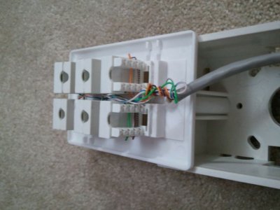
Use this photo for a reference.
2010-12-29%2018_36_29.jpg

As you look at the 2 visible keystone jacks in the photo they each have 8 connectors. On each keystone, the 2 connectors in the row closest to the face plate are pins 8 and X, but this X does not matter. In the second row from the face plate are pins 1 and Y, again the Y does not matter.

I took a single long wire and tied all of the pin 8s and their X pins together making a long series wiring string. I then placed my conductor coming from my mini-din pin 8 to a single keystone pin 8 and its X.

I then took each switch input conductor (1-6) from the mini-din and placed it across pin 1 and its Y on each keystone. You now have a unique wire on each keystone pin 1 and all keystone's pin 8 tied together.


You do not need a punch tool for the keystones. Each keystone comes with a plastic cover to protect against shorts. This cover is also used to force the wire into the connector acting as a punch down tool.


You could avoid wiring to the X,Y pins but it would make the job more difficult and frankly, Why? It works, is it easy to wire, and you won't use the X,Y pins.
 
The extra explanation on how to wire the keystones helped. Any tips on getting the pins out of the plastic holder? I tried pushing them, pulling them and warming them up with the soldering iron and no luck. I bought the same part as shown here.

Thanks
 
The extra explanation on how to wire the keystones helped. Any tips on getting the pins out of the plastic holder? I tried pushing them, pulling them and warming them up with the soldering iron and no luck. I bought the same part as shown here.

Thanks

Have a decent set of needle nose plyers. Grasp the pin close to the holder as seen in of my previous photos. Push. You'll feel a small pop as the pin starts to move, the pin has a ridge to lock into the plastic holder you need to overcome.

As for iron assistance, I placed the tip of the iron in the solder cup while pushing twords the plastic holder. As soon as it starts to move grasp the other end with the needle nose and use the above method.

I had better results without the iron, it's tricky to get the heat correct without over heating.
 
can i ask why you use audio jacks? how would these work on pumps or float switches for top off.

sorry, new to this stuff. can anyone explain how you connect devices to the break out box.
 
can i ask why you use audio jacks? how would these work on pumps or float switches for top off.
sorry, new to this stuff. can anyone explain how you connect devices to the break out box.
the audio jacks are easy (as they are only two wire connectors). One wire goes to each of the ears of the connector, when plugged in, the input devices are properly wired...


jrpark22000 (in his box) would use an RJ45 jack crimping tool (used to make Ethernet cords) to add an RJ45 jack to any float switch.

in his example, he'd just put one wire in the far left pin slot and one wire in the far right pen slot and crimp.. he'd have a float switch that terminated in an RJ45 connector (again, looks like an Ethernet cable) that when he plugged into his breakout box would connect properly to the Apex switch. (designated by the location in his breakout box)

when he plugs his breakout box into his apex, he can immediately begin using Switch1, Switch2, Switch3, etc as conditions in his programming..

If Switch2 CLOSED Then ON (as an example)
 
As mentioned earlier in the thread, the cost of supplies vs the neptune product will vary depending on what you (or your friends) have laying around.

The one bonus to building the box yourself is a cleaner/finished look. Both designs in this thread and the Neptune design work the same, but the design's here are clean, since you just plug into a jack, instead of "clipping" a bare wire into the unit. It's all a matter of how you feel about it visually.

I have my Apex, Breakoutbox, and Mp40w controller, and wireless card mounted on the back outside of my stand as there was no room inside without being "Plasticman". So I obviously didn't want anything looking, what I feel, is ugly.

On another note, it's nice to see that people are still getting something out of this thread, as well as adding to it :)

/D
 
Just built mine and it is working perfectly for ATO (DIY with float swtich and aqualifter pump) and leak detector (DIY with 2 wire thermostat wire).

Thanks for the instruction guys. Really helpful!

IMG00160-20110406-0024.jpg
 
Hey guys, i need a help.

According to this link: http://www.neptunesys.com/index.php?option=com_content&task=view&id=48&Itemid=48

The Aquacontroller uses just 4 pins of the MiniDin 8-pin cord. So, if i wonder to do my own cable, can i just use 4 wires?

If not, which of the 3 grounds should i use in my DIY?


Am i clear?
Tks.
If you are talking about the Apex here are some links and page numbers for the mini DIN-8 plug: Neptune Page 51 and the Unofficial New User Guide for the Apex AquaController Page 84.

HTH

Jay
 
While I do not have an Apex (I'm an RKE guy), I like this.

I like the RJ-45 box the best, but if you went
with RJ-11 you could use standard telco wires
 
While I do not have an Apex (I'm an RKE guy), I like this.

I like the RJ-45 box the best, but if you went
with RJ-11 you could use standard telco wires

that's what I did... an RJ-11 will plug into and correctly align with an RJ45's pins 2-7 (if you're using a 6 wire RJ-11, it will align with 3-6 if using a 4 wire, it will align with 4-5 if you're using a 2 wire)

I used RJ-11 jacks on the ends of my float switch wires to hook into the box..
attachment.php


attachment.php
 
Back
Top