DIY LED driver for reef lighting

This is the first I have seen documented that LEDs (may) have a color shift based on current. Does any have or has seen this in the LED data sheets (maybe I missed it). This could affect the coral growth and explain why some have better luck than others.
 
I've seen plenty of documentation hint at the potential shift (but not quantify it), but I can't detect it with my naked eye when turning a knob on an LED fixture, or running two side-by-side with different sense resistors, both of which I've done plenty of times using this driver design, which would have revealed the difference between PWM dimming (i.e. pulsing a high drive current to the LED at above-visible frequency to give the appearance of dimming) and just running at a lower drive current.

At any rate, given actually-visible variation from other sources (namely, the variation in color from batch to batch of a given LED, and that caused by different combinations of different models/colors of LEDs) I doubt the variation caused by low drive current has a significant impact.
 
Use the normally open set of contacts so that when the relay is off, no power can flow.

Energize the relay to activate the lights.

That's what I was thinking too. But the relay will consume energy while it's on (the whole time the lights are on). That energy consumed equals some amount of watt-hours. Now when the lights are off and the relay kills power to the driver, how much energy are you saving? Is it more than was consumed by the relay throughout the day? If yes, then it's practical to use the relay. If no, then you are actually being less efficient by using the relay.
 
what voltage are people running their power supply at. Is 24v optimal below that the LEDS don't seam bright enough. raising the voltage to like 26v seams to make it quite a bit brighter. I am using DWZM's driver design. I am only running 8 LEDS on my 150 right now will the shimmer effect be less when I add more LEDS. Seams like it shimmers like crazy now. Also what temp should the LEDS be below. They only read a couple degrees hotter than room temp.
 
what voltage are people running their power supply at. Is 24v optimal below that the LEDS don't seam bright enough. raising the voltage to like 26v seams to make it quite a bit brighter. I am using DWZM's driver design. I am only running 8 LEDS on my 150 right now will the shimmer effect be less when I add more LEDS. Seams like it shimmers like crazy now. Also what temp should the LEDS be below. They only read a couple degrees hotter than room temp.


go back and read post 157
 
what voltage are people running their power supply at. Is 24v optimal below that the LEDS don't seam bright enough. raising the voltage to like 26v seams to make it quite a bit brighter. I am using DWZM's driver design. I am only running 8 LEDS on my 150 right now will the shimmer effect be less when I add more LEDS. Seams like it shimmers like crazy now. Also what temp should the LEDS be below. They only read a couple degrees hotter than room temp.

Can you measure current and voltage on the output side? What Rsense value did you use, and what current do you THINK you're running at? If adjusting the voltage makes a difference in output, it means one of two things has happened:

1) The driver just plain isn't working - the switch isn't switching, and you're just passing the input voltage straight through to the LEDs (minus a small drop from the resistance of the circuit). This can happen because of incorrect or broken components. Earlier in the thread, I mentioned my first prototype had the wrong timing capacitor. It acted like you're describing.

2) If you're using an Rsense value to create a VERY low current, it will be very easy to overdrive the driver. Since this is a boost driver, it needs an input voltage lower than the output voltage. If it gets an input voltage that's too high, it'll just pass that voltage through to the LED string.

If you're running 8 LEDs and adjusting the input voltage makes a difference over the range you're describing, I'm worried that it's #1, not #2. Did you double-check all your component values? What current are you trying to run at, and what current are you seeing on the output side?

Keep in mind that you're treading on dangerous ground when you turn the input voltage up. Make SURE you know the characteristics of the LEDs and what their Vf would be at their max rated current, and NEVER supply the driver more than that, or you'll blow everything up. ;)

PS if people are having any problems at all, please report them in the thread - that way, the troubleshooting experiences can be valuable to anyone else who might be trying to design.
 
Well I've had this setup running for 24 hours now and haven't blown the LEDs up yet. I kept it at 24v to be safe. I have the driver set up for 700ma. Ill recheck all my connections and values of components to see whats going on.
 
Well I thought I was missing a jumper, Soldered in one and reconnected it to the power supply. Few seconds latter the chip went poof. Now Im back to square one.
 
Where'd you put the jumper? Are you using the PCB we've been discussing in this thread, or just the generic NCP3066 design on some other PCB? Care to post some pics?

This is probably worth noting for those prototyping their own layouts. I used a socket for the IC so I could remove it during soldering, and swap it out without having to resolder if I blew it.
 
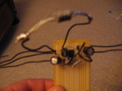
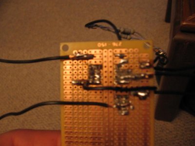
Here are some pics. Kinda sloppy on a Radio shack proto board. The jumper was from pin 6 to 24vdc and one from ground to the caps. Now that i look at this again i might have had the chip in backwards. What do you think?
 

Attachments

  • IMG_0871.jpg
    IMG_0871.jpg
    49.3 KB · Views: 10
  • IMG_0872.jpg
    IMG_0872.jpg
    41.4 KB · Views: 14
Can you get a clearer shot of the topside? That looks pretty similar to the layout I had for my protoboard versions.

Pin 1 is to the left of the notch on the chip. That's the switch collector. Pin 8 is to the right of the notch. That's the PWM input. So, if the notch is between those two connections, it's right. If the notch is between GND and COMP (Rsense) you've got it backwards.
 
I used the schematic on post 62. Now that I look at it again it looks like the view from the bottom side of the board. So I made that board from the top side and my pins are all messed up. My pins should be swapped side to side. Right now my pin 1 is where pin 8 is on that schematic.
 
The holes for the schottky diode were quite a bit too small - enough that I had to drill out the whole diameter of the pad to get it to fit.

Copy that. I just ran into the same issue with the diodes - and I was using the correct drill sizes for those holes. I think the Eagle part I used must have had thinner wires [sigh]

The datasheet isn't particularly informative though. It says the leads are 0.032" diameter (maximum), but recommends a hole diameter of 0.1" (!)

Oh well, there's not *too* many parts to go through and check...

Simon
 
Don't want people to think I've forgotten this thread - I'm having some "issues" with getting the gerbers to the board house. The CAM job they want me to use puts the drill holes in the wrong locations. They don't want the gerbers I generated with sparkfun's job. To be fair, it's probably something stupid I'm doing, not something wrong with them.

In the meantime, user perikaruppan has brought another chip to my attention:

http://www.diodes.com/zetex/?ztx=3.0/product_portfolio@pno~ZXLD1366

It's surface mount, but an "easy" package, and it's a much simpler design (fewer parts) and can go up to 60v (though it would be tough to find a power supply at that voltage for the same price as we can get 24v supplies.) It looks a little less stable than the NCP3066, and the package looks a little more thermally sensitive, but the design is so simple it should be easy to get something working. Efficiency looks similar. Dimmable via PWM or analog, though the analog dimming is really wonky (it's over a VERY small range and it looks like it would be easy to "accidentally" overdrive the LEDs).

Anyone else used or at least looked at this chip? It IS more expensive ($4.30 vs $1.50) though due to the low parts count, the cost per driven LED wouldn't be THAT much different.
 
Look at the graphs around halfway through - the output current varies a "fair" amount (a few percent) based on input voltage and some other conditions. The NCP3066 has some variation too, but not quite that much.

Has Evilc66 actually used this chip?
 
Yes, evilc66 has mentioned to me that he has used this chip and has found it working well especially the ZXLD series. I have narrowed it down to ZXLD1366 or 1362. And he has mentioned to use the circuit in the Datasheet and use the XLS sheet to determine the values of the components.
 
Last edited:
Back
Top