DIY LED driver for reef lighting

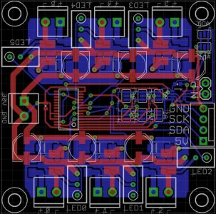
I'm working on an 6 driver PT4115 based board with a PCA9685 to do the dimming and TMP421 for temp sensors. Since I was running 2 I2C slave devices on one board and then going to a remote master I wanted to read up on the I2C stuff a bit more. I found several forum posts and these tutorials that stated that 1m was the limit for I2C.

http://tronixstuff.wordpress.com/2010/10/20/tutorial-arduino-and-the-i2c-bus/
http://tronixstuff.wordpress.com/2010/10/29/tutorial-arduino-and-the-i2c-bus-part-two/

A lot of those tutorials aren't real world so I trust your real world experience with the distance. I'm short on board space anyhow so I'll leave out the I2C extender and if I end up having issues I can always add on external I2C extender boards.
 
if I end up having issues I can always add on external I2C extender boards.

Or switch to better cabling, or switch to stronger pull up resistors or lower speeds. There should be lots of options and I wouldn't seriously worry unless you had a REALLY long run. I've heard of people going hundreds of feet with careful system design.
 
Couple of quick question on the I2C stuff. I'm going to run the 5v power and ground from the arduino master along with the SCK and SCL lines.

Do I put the pullup resistors on the master side before connecting to the arduino or put them close to the slave I2C devices?

Next, on the driver board I'll have two voltages, 6v-30v coming in for the LED drivers and 5v coming in from the arduino. Can I use a common ground or do I need to keep the 5V ground from the arduino isolated from the 6V-30V ground?
 
Last edited:
Originally Posted by S2minute
I was woundering. Can any of you program an Arduio(s) with an LCD to do this:

Hi, i'm involved in a DIY LED light fixture project for a reef aqurium. This fixture is 6' long and has 3 sections.
each section has 48 leds for a total of 144. These leds are arranged in series strings of 6 leds each string. Each string will be driven by a CAT4101. Three of the strings however will be all XM-L LEDs @ 1.5 amps and will need to be driven by 2 CATs as each CAT is limited to 1 AMP. The documentation for the CATs states that 2 CAT drivers can be run together for a total of 2 AMPS. The remaining 21 strings will be driven by their own CAT driver. I have 4 CAT driver boards that have 8 CAT drivers each. The LEDs on each of these strings will all be driven @0.7 MA. The PS for the 3 XM-L LED strings will be a Meanwell SP-100-24 @4.5 amps adj +/- 10%.
The remaining 21 strings will be driven by 2 Meanwell SP-320-24 @13A. 10 strings on one PS, the remaining 11 on the other. The Meanwells run on PWM.
What i'm trying to accomplish with an Arduino(s) is to simulate sunrise/sunset via a realtime clock on a LCD display. I would like to accomplish this by dimming UP from east/west one string then the next as to better sim the sunrise with the 3 XM-L LED strings dimming up last to sim mid-day then dim down as the noon day sun progresses. I can do this as the 3 XM-L strings run perpendicular to the rest of the strings and span the 6' length of the fixture. I would aslo like to sim cloudy days, stomy weather and DEFINATELY the lunar cycle.

I really want this for my new fixture. If anyone can tell me what to script in and what hardware i need, i can put it together myself...i believe Or if anyone can do it quick i can send them what they want for their troubles
Thanks.
 
I wonder if anyone has used Texas Instruments (TI) WEBENCH to try to get their values for Coff, Roff, Rsns etc. etc..
Here is what I get from it and when I compare it to Terahz design, values of some resistors are very different. I'm currently investigating where is the catch but if any quick eyes can spot it I would appreciate.
I find WEBENCH every interesting, it even allows you to run simulations of the circuit and get graphs of Iout, Vout etc..

WEBENCH Design
 
Couple of quick question on the I2C stuff. I'm going to run the 5v power and ground from the arduino master along with the SCK and SCL lines.

Do I put the pullup resistors on the master side before connecting to the arduino or put them close to the slave I2C devices?

Next, on the driver board I'll have two voltages, 6v-30v coming in for the LED drivers and 5v coming in from the arduino. Can I use a common ground or do I need to keep the 5V ground from the arduino isolated from the 6V-30V ground?

I haven't seen anything that indicated a preference for location of the pullups. I've always put them on the same PCB as the master since they only need to exist once (i.e. vs putting them on a PCB with a slave device) and that's a convenient way to do it.

The grounds need to be common.

I really want this for my new fixture. If anyone can tell me what to script in and what hardware i need, i can put it together myself...i believe Or if anyone can do it quick i can send them what they want for their troubles
Thanks.

What you are describing is definitely possible, but depends more on the controller design than the driver design - you might get better luck posting in one of the controller threads.

The way I would approach this would be to use a Typhon or other Arduino clone as a "master" and have it drive an LCD, allow for user input, and so on. Then put a bunch of simple Arduino clones on the I2C bus to allow for more PWM outputs. You could use a custom design, a Typhon without the LCD or RTC populated, or something commercial like the RBBB. I'd probably just do it all on Typhon PCBs since you're probably gonna end up with 10 or 12 of them if you go with seeedstudio or iteadstudio.

when I compare it to Terahz design, values of some resistors are very different.

To help our eyes operate more quickly, can you point out which resistors had different values, and which of Terahz's designs you are comparing to?

As a total shot in the dark I'd guess Roff is the one that's different because the frequency you chose was different than Terahz's. That's really the only resistor that could possibly be wildly different for the same general operating parameters.
 
Thanks DWZM for looking into this.
It was value of Ruv1 that was different. Since then I have dissected whole design and I "think" I understand the whole design. :) :) I was looking at version 0.6 of terahz design.
Now what I have gathered from documentation ,and I cold be totally wrong, is that value of Ruv1 sets Vturn-on of he chip and current value of Ruv1=6.8KOhm turns it on at ~10V.
Since terahz design is setup to have Vin=42V don't we want to have value of Ruv1 so that it turns chip on at ~40V and not ~10V.
Looking back at documentation even they have 2 examples one with Vin=35V and one with Vin=14V and both are using the same values Vturn-on =~10V.
It talks about it in documentation under "INPUT UNDER-VOLTAGE LOCKOUT (UVLO)"

I don't know if this has any implications and it might be totally unimportant.

Just to add, WEBENCH has value of Ruv1=16.5KOhm which puts Vturn-on=5V.. Beats me if I understand where they get these values.. :)


Can someone look at this worksheet and tell me if everything is ok.
This is for:
Each driver will drive 2 Cree XM-L @1.5A
Vin - 13.5V - 15V
Vout= 6.4V


LM3409_worksheet
 
Last edited:
I'll take a look, but for what it's worth, I've never fiddled with the UVLO resistors.

The design you posted above has an operating frequency just above 1mhz, that strikes me as extremely high. I'd aim for ~500khz.
 
Thanks DWZM..
You mean design from WEBENCH has 1Mhz? Yes, I saw that but there is no option to change it.. Anyway, I'm not using that anymore as it's very limited what you can set for your design. It's good general tool but nothing more..
In my worksheet, I'm aiming for 200Khz just like everyone else.
 
I felt the same way about that design tool. It's an interesting way to get to know a chip without having to do all the math but it's (unfortunately) limited. It looks like it's come a LONG way since the first few iterations though so hopefully they will continue to improve it.
 
Hi,
this thread is enormous - amazing!!!
I understand two important features:
1) I could extend this driver up to 5A
2) I dont need analog outputs - instead I can run unlimited?? drivers just over I2C
Is this all correct?
ALso - it says it supports 12 Bit dimming - the arduino only supports 8 Bit dimming. Since the drivers use I2C - can I also dimm with 12 Bit using arduino?

Sorry, I assume to find all answers in the thread but as I said - enormous work!!!!

I checked this schematics:
https://github.com/TeraHz/I2C-LED-Driver
What would I need to change to get it to 2A instead of 1A?

Thx
 
I haven't seen anything that indicated a preference for location of the pullups. I've always put them on the same PCB as the master since they only need to exist once (i.e. vs putting them on a PCB with a slave device) and that's a convenient way to do it.

The grounds need to be common.
So no danger in frying the arduino by combining it's ground with my 30V power source ground?
 
Hi,
this thread is enormous - amazing!!!
I understand two important features:
1) I could extend this driver up to 5A
2) I dont need analog outputs - instead I can run unlimited?? drivers just over I2C
Is this all correct?
ALso - it says it supports 12 Bit dimming - the arduino only supports 8 Bit dimming. Since the drivers use I2C - can I also dimm with 12 Bit using arduino?

Sorry, I assume to find all answers in the thread but as I said - enormous work!!!!

I checked this schematics:
https://github.com/TeraHz/I2C-LED-Driver
What would I need to change to get it to 2A instead of 1A?

Thx

1) In theory it'll go up to 5A, but component selection starts to get really, really hard when you get above 3 - 4 A - unless you come up with a new board layout that uses bigger packages.

2) The IC itself will accept analog or PWM input. Terahz's earlier designs allowed you to supply PWM and have it converted to analog and fed into the driver's analog input. His later design uses an I2C chip to create the dimming signal. You can only put 8 of them on the same bus (address limitations for that chip) unless you come up with a clever address switching method - terahz posted a link to such a chip back a page or two.

The Arduino's 8-bit limitation is on it's own PWM output pins. The I2C driver terahz posted relies on an I2C interface which has 12 bits of resolution, so it's not limited by the Arduino's PWM pins.

If you keep Vin-Vout the same, generally you can change the Rsense part to get different currents, but it's always a good idea to get the design spreadsheet that's been linked earlier in the thread and run the numbers to make sure.

So no danger in frying the arduino by combining it's ground with my 30V power source ground?

No, as long as you're just connecting the grounds. In fact since there are portions of your system that see both voltages you NEED to have a common ground.
 
I found that the WEB bench cr@ped out at like 1A when trying to do stuff with the 3409. Rather annoying. Also annoying that National Semiconductor sold out to TI. Bleeeeelgch!
 
Okay, so here's my first stab at board and schematic for a 6 driver 5cm x 5cm PT4115 driver. Each driver can output 1.2a max and 30v max, so a max of 7 LED's per driver.

I made it so you can get the cheap $2 PT4115 drivers from DX, strip off the parts, and use on this board. It only takes about a minute to pull everything off. It reuses the PT4115, diode, inductor, and if you only need 750ma the current sense resistor.

The board uses the PCA9685 which is an I2C part that does 12 bit PWM. It also has a TMP421 temp sensor that will give you the temp of the board and has a hookup for an external temp sensor. This is also an I2C part.

I'm new to Eagle so there are some air wires that I couldn't get to go away even though everything is connected up. Also some overlap warnings where there shouldn't be any. If someone more experienced with eagle wouldn't mind taking a peak and telling me what I did wrong I would be eternally grateful.
 

Attachments

Okay, I got all the airwires issues resolved. It was because I was using a very small grid size so things weren't snapping like they should have and completing the airwires. Ripped up some stuff and redid with a larger grid and issue solved. I'm also reducing the size of the chip wires and I need to add a couple more jumper pads for setting the address of the TMP421. I'll upload again once I'm done.
 
New version with address jumpers for the temp sensor, no errors in schematic or board, and nothing in ratnest. Would appreciate any feedback from the pro's before I send it out to seeedstudio.
 

Attachments

  • PT4115_LED_Driver_v.02.zip
    PT4115_LED_Driver_v.02.zip
    61.5 KB · Views: 10
  • PT4115_LED_Driver.jpg
    PT4115_LED_Driver.jpg
    110.3 KB · Views: 11
Hello first I must say nice work man well done.

Next :

I need SW for my arduino my idea about the functions is this :

http://www.youtube.com/watch?feature=player_embedded&v=vHo7LTgkbZ4

what I have in home :

RTC for Arduino
Arduino Uno
Power 12V for arduino

LED ramps - 5modules(pads). each module have a 3lines of Cree LED , 2line together on the sides - Royal + Blue, in the middle is whites.
each pad have together 18x 3W Cree LEDs , 12pcs RB+B and 6Whites. led will be controlled by Cat4101 , 1pcs on 1line.
Power supply for this led ramps is Meanwell SP 320-24.

Controling wia USB, Ethernet , or BT.

I need do for this setup program can anyone do this?
 
Back
Top