I have a question about multiple strings of leds. After reading this thread, I have decided to go with the cat4101 board with separate pwm. I want to connect multiple strings with different voltages to the same power supply. Each driver board will have the same leds. Can I use something like this http://www.ebay.com/itm/4-5-24V-0-93-20V-2A-DC-DC-Converter-Step-Down-Buck-Module-Voltmeter-/150843486243?pt=LH_DefaultDomain_0&hash=item231ef8f023#ht_1961wt_1180 to control the voltage to each driver?
You are using an out of date browser. It may not display this or other websites correctly.
You should upgrade or use an alternative browser.
You should upgrade or use an alternative browser.
DIY LED driver for reef lighting
- Thread starter der_wille_zur_macht
- Start date
Can you give a better description of your proposed led layout with the number of Cat4101's and the type of leds that you plan to run? Depending on that info, there may be a better way to go about laying things out.
The DC/DC step-down convertor that you linked has some specs that seem suspicious. They list it as having a continuous 2 amp output, but it's only rated at 20 watts total output. Simple Ohm's law says 2 amps X 10volts = 20 watts. That leaves you only 10 volts for your leds, so your strings could only comprise 3 leds. In order to run 6 leds per string, you'd need 20 volts @ 1 amp. Simple math doesn't lie, and a $9 a pop for the dc/dc convertors, your money may be better spent buying more 24 supplies and skipping the dc/dc convertors all together.
The DC/DC step-down convertor that you linked has some specs that seem suspicious. They list it as having a continuous 2 amp output, but it's only rated at 20 watts total output. Simple Ohm's law says 2 amps X 10volts = 20 watts. That leaves you only 10 volts for your leds, so your strings could only comprise 3 leds. In order to run 6 leds per string, you'd need 20 volts @ 1 amp. Simple math doesn't lie, and a $9 a pop for the dc/dc convertors, your money may be better spent buying more 24 supplies and skipping the dc/dc convertors all together.
Can you give a better description of your proposed led layout with the number of Cat4101's and the type of leds that you plan to run? Depending on that info, there may be a better way to go about laying things out.
The DC/DC step-down convertor that you linked has some specs that seem suspicious. They list it as having a continuous 2 amp output, but it's only rated at 20 watts total output. Simple Ohm's law says 2 amps X 10volts = 20 watts. That leaves you only 10 volts for your leds, so your strings could only comprise 3 leds. In order to run 6 leds per string, you'd need 20 volts @ 1 amp. Simple math doesn't lie, and a $9 a pop for the dc/dc convertors, your money may be better spent buying more 24 supplies and skipping the dc/dc convertors all together.
I am trying to utilize my existing power supply(generic 24v 6.4a) keeping everything simple. On one power supply I would like to run a string of 6 cree white xpg, a string of 6 blue xpe, a string of 4 green xpe, and a string of 4 xpe red. Each string will have its own driver all driven at .7A. I've read that power supply needs to be close to the Vf of the led string not to overheat the cat4101. Of course I am not very knowledgeable on this topic and my current led setup was created following directions from the original led thread. Thanks for your assistance.
I had some down time a work a few weeks back, so to fight the boredom I fired up my EAGLE software and created this.
It's a 6 channel CAT4101 Led driver PCB with an ATMEGA328P-AU and a DS1307 RTC built in.
It also includes a 12volt /1.5 amp regulator for powering cooling fans ect.. and a 5volt reg to power the CAT's and the microcontroller.
All the pins on the ATMEGA chip are broken out for use, just like an "œoff the shelf" arduino, so adding additional functionality is just a bit of extra wiring and coding.
The Board includes a FTDI connection for programming purposes and an I2C connection for expansion.
I chose to include 6 CAT4101's since that's the number of PWM outputs available on the ATMEGA chip.
The Micro-Controller portion of the board is thermally isolated from the rest of the PCB, as it sits in it's own Polygon with just a small ground trace connecting it to the rest of the board.
The CAT4101 chips sit atop 3 large vias that will conduct heat to the bottom plane of the PCB and ultimately to a dedicated heat sink.
The CAT4101's PWM inputs are brought out to a six pin female header, instead of being hard wired directly to the ATMEGA.
I designed it that way to keep my options open with respect to different PWM connection configurations.
Each CAT 4101's current output is fully adjustable from around 50ma to 1000ma maximum by turning a 10k trimmer pot that's soldered inline with a 549ohm resistor.
I built three of these to replace the current CAT4101's that have been driving my leds for the last 2 years or so.
My current led lighting system is comprised of 90 "œancient" Cree XR-E Q5 leds driven in groups of 6 by 15 CAT4101's.
I'm not very good at writing code for the arduino yet, but I plan to learn how, as I would like to configure each ATMEGA chip as a "œslave" to a "œMaster controller" via I2C some time in the future.
For now each of the three driver/ controller PCB's has been programmed to run independently, with varying or staggered "œon/off" and "œfade duration" times to simulate "œsunrise/sunset".
They've been running that way for the last two weeks and seem to be performing well.
Let me know what you guys think?
I had some down time a work a few weeks back, so to fight the boredom I fired up my EAGLE software and created this.
It's a 6 channel CAT4101 Led driver PCB with an ATMEGA328P-AU and a DS1307 RTC built in.
Let me know what you guys think?
Very cool!
Would like to see it in your enclosure.
== John ==
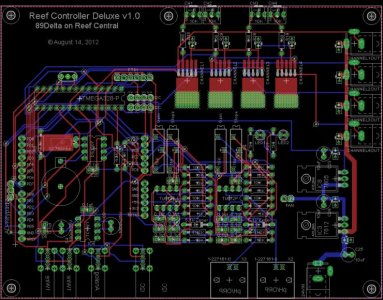
O2Surplus.....i've done something similar to your 6-channel controller. Mine is 4-Channels though currently as i'll be using an I2C 20x4 Display. It also has pH and ORP capability as well. For input i'll be using a ADC-Keypad. Here is what I have so far....
Attachments
O2Surplus.....i've done something similar to your 6-channel controller. Mine is 4-Channels though currently as i'll be using an I2C 20x4 Display. It also has pH and ORP capability as well. For input i'll be using a ADC-Keypad. Here is what I have so far....
Way cool! I was planning to use an I2C LCD and buttons too. I like your design, but I didn't add any more functions to mine for fear of making it overly complex. I figured that if I passed them out to a few friends, they could choose how many additional components or functionality to add for themselves. Since all the pins are broken out going from "mild" to "wild" with the arduino portion of the board is totally doable.
Landsailor
New member
Let me know what you guys think?
I think that is covered in awesome sauce, O2!
What was the cost per board?

Landsailor
New member
How'd you get a white board or is that a paper label?
It looks like he just made a negative of the silkscreen layer.
How'd you get a white board or is that a paper label?
Hey Kcress- I was getting bored with plain old "green" so I blew an another $10 for "white". I had the PCB's made at SeeedStudio, but I think that "white" is a fairly new color option for them, as I hadn't noticed it until recently.
Okay I'm just beginning the long journey down this thread. Can anyone point me to the "final" version of the CAT4101 driver for a single channel? It is going to take me a day or two to read and digest this thread. Digesting mistakes only to find out later they are mistakes is time consuming. Any help would be appreciated.
There is no "final" version of the CAT4101 based driver. There are plenty of designs posted in this thread that are correct for the people who designed them. This thread documents the evolution of many of them. If there's a particular design consideration that you need, just ask, and may be one of us will already have what you want.
I found the answer to my questions a few pages later. I was merely confused for a bit. I'm still designing the whole fixture. I know what I want I just need to figure out how to build it. As far as a driver I want 12+ channels, although some will be left unused. I plan on dimming with an Arduino controlled PWM signal. I'm looking at 96-120 LED's. At least 8 colors, although I think that will increase. I still have to figure out the emitter half so the exact number of channels and LED's per channel is up in the air. I see no reason I wouldn't be able to accomplish this, I've just got to get through the rest of this thread to figure out how.
As an aside the wealth of knowledge in this thread is pretty remarkable, and I'm only ~20 pages in. It makes these things quite accessible for those with a limited knowledge of electronics, like me. Although by the end of my build I think my knowledge will be a little less limited.
As an aside the wealth of knowledge in this thread is pretty remarkable, and I'm only ~20 pages in. It makes these things quite accessible for those with a limited knowledge of electronics, like me. Although by the end of my build I think my knowledge will be a little less limited.
BeanAnimal
Premium Member
Jerpa,
We can talk about your plans at the meeting. Do you have any electronics experience or is this you first project?
I have a oscope, soldering stations, bench supply, meters and other goodies like a stereo microscope and beer.
We can talk about your plans at the meeting. Do you have any electronics experience or is this you first project?
I have a oscope, soldering stations, bench supply, meters and other goodies like a stereo microscope and beer.
Basic high school electronics, a strong foundation in math, the ability to grasp things pretty quickly, and the naive belief that I can do/learn anything I put my mind to. That's all I'm working with. I'm currently brushing up on my electrical theory. Electronics for Dummies and Practical Electronics for Inventors are being read as we speak. Lol.
BeanAnimal
Premium Member
I have some electronics books you can borrow if you need (and likely dozens or more ebooks). If I remember, I will bring them to the meeting.
Similar threads
- Replies
- 0
- Views
- 83
- Replies
- 6
- Views
- 851
- Replies
- 20
- Views
- 2K