DIY LED driver for reef lighting

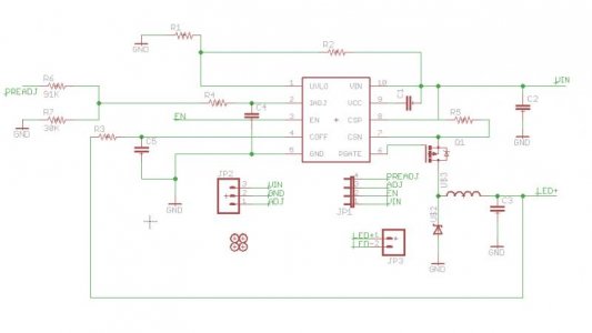
Well, the IC itself can be found for less than $1.5 which is less than 1/2 the price of the CAT on mouser and digikey and still cheaper than the lowest price I'm able to find for it. It is very likely, however, that by the time the rest of the components are added, the prices will be very similar so that's not a big advantage. However the LM3409(HV) can drive XPGs and XMLs at their highest current, if needed. The HV version of it, can also string quite a few LEDs together by accepting up to 75 Vin (20+?) so if you can find the proper PSU, it might be a good option for people with more LEDs who don't want to end up with dozens of CAT boards and many times more wires going to their LEDs.

The main reason I want to give it a try is the non-PWM dimming. Given that almost half of the time my LEDs are in some form of PWM, I believe that the corals will be much happier if they get a constant light source over bursts of blasting with light and then turning the light off.

Also, for my situation, I have 8 CATs driving 6 LEDs each, running 16 wires between drivers and LEDs and at least 6 wires from controller to CATs (Gnd, 5V and PWM for each board of 2 CATs). If I use the LM3409s I might get by with only 2 chips (one for blue, one for white), running 4 wires to the LEDs total and 4 wires from controller to LEDs. I know that this will probably not fly because I don't think a 75V 3A psu can be had for reasonable price. However even if I do 1:1 substitution of the CATs and LM3409s, I don't have to worry about adjusting Vin to match the LEDs.

Also it is fun to make new stuff :)
 
I don't see those prices on digikey, but the CAT can be found at Future Electronics for $1.92 or 10 + for $1.80.

I do like the sounds of the higher voltage and current. Maybe a 48 volt supply would work well - that also keeps it under 50 (sort of the recommended newbie limit according to kcress).

I solved the non-PWM dimming with a trimmer pot for the Rset of the CAT4101 and so far no problems.

I agree running wires is a bit of a pain, but I placed my board in the fixture and since it has a 5 volt regulator I only need to wire the 24 volt supply and each string. I have yet to get the PWMs working (no controller).

Please let us know how it turns out. This might be a good option for large builds.

One more thought some might consider it an advantage to have more strings. If one string goes out you still have only lost some (1 / number of string) rather than half your lights.

Hmm, as I read back over what I wrote it sounds like I am picking on each of your points, don't mean to sound that way just trying to propose options so people can make informed decisions.
 
Fishman, I am running your board with the trimmer POT and using a controller for PWM and have absolutely no problems (minus still needing another board, wink, wink). LED's are running strong and so far so good.
 
TheFishMan65,
Yes, Future has the lowest price for the CATs, but as I said, that is still more expensive than the price of the LM3409 (again at Future, I think). I do expect the final board to be more expensive than a final board with a single CAT, but cheaper than the triple channel CAT board that almost everyone is using.

Regarding dimming, I was referring to the daily sunrise/sunset, rather than setting the max. A trimpot will certainly work for setting the max, but not for control via micro (I assume you are talking about a regular trimpot and not some IC).

I considered moving my drivers to the lights, but I don't have any covers for them yet and it will be too ugly :).

In the end I've been using the CATs for about a year now and have no complains other than the stated PWMed output during dimming and possibly the bundle of wires that has to go to my LEDs (though after I moved to 2 ethernet cables, it is much simpler now). I just like to try new options and the LM3409 sounds like a nice chip. If it works, it just means more options for people to choose from.
 
So you are looking for true analog dimming for sunrise and sunset kind of like the ELNs. I thought about trying to use some sort of IIC potentiometer, but could not find one I thought would work.
 
Ok, here it is. As I said, basically reference design with a voltage divider for the analog input (current resistor values are for 5V in). Also added a couple of jumpers to allow for either PWM or Analog dimming. I'll play around with a board design probably on the weekend and will put together a bom.

attachment.php
 

Attachments

  • v01.jpg
    v01.jpg
    26 KB · Views: 10
Need advice from experts.

Im running 6 cree XP-e royal blues at 700ma. Supply is 24V. I adjusted it down to the point where light starts do dim and then back a notch.
Cat4101 gets hot. Its painfull to hold finger on heatsing for longer period. Good thing I put heatsink. Should it be that way ?
White string is driven at 350mA and runs barely warm.

Regards
 
Its 16,8V to ground :fun5:

:uhoh3::uhoh3::uhoh3::uhoh3:
That does not sound right. That would mean the LEDs are only dropping about 7 volts (24 - 16.8). But if true that would be 0.7 amp * 16.8 volts or 11.76 watts the CAT is dropping which would explain why it is getting hot.

Let's see if these will tell us anything:
How many LEDs in a string?
What is the voltage across the entire LED string?
What is the voltage across the power supply?
 
DIY controller

DIY controller

I am in the process of ordering LEDs for my tank.
48 XPE-RB and 24 XRE-O5 CW for a start. My question is are the DIY drivers only good for 6 LEDs
or is it possible to build a driver to handle 12? It seems that you end up with a lot of drivers. It's
been a long time but I do have some experience assembling electronics.
First post, Clif

The drivers are designed to ru 6 LEDS per Cat and there are 3 Cats per driver. So 18 LEDS per driver if built to spec.
 
That is not exactly true. There are as many CATs as you design on the board. Mine has 8, someone else just asked me a question and plans to design in 5. 3 was what DWZM thought was best and is the board available if you order your own and don't have tools (or want to) design one.
 
AWESOME THREAD!!!

I'm a noob to RC and to Ref Keeping. I am trying to setup my first Reef Tank. I am obsessed with doing LEDs. This thead is totally awesome, it reads better than a Harry Potter book. Only on page 11 right now but hopefully I can catch up. I have searched obessively for months for a good thread and this definitely it.

Keep up the great work guys. Once I can catch up, I would like to get some boards from anyone who has any.

-Phillip
 
:uhoh3::uhoh3::uhoh3::uhoh3:
That does not sound right. That would mean the LEDs are only dropping about 7 volts (24 - 16.8). But if true that would be 0.7 amp * 16.8 volts or 11.76 watts the CAT is dropping which would explain why it is getting hot.

Let's see if these will tell us anything:
How many LEDs in a string?
What is the voltage across the entire LED string?
What is the voltage across the power supply?

After playing with pot I,ve gotten:

6 leds in a string
18.8 V across LEDs
22 V PSU
3,1V now is pin 5

Cat is hot as hell anyway. The question - why only 18,8 acrooss leds.
If I try to get more than 18.8 cat gets even hotter.
 
If I try to get more than 18.8 cat gets even hotter.
You are dropping 22 - 18.8 = 3.2 volts across the CAT (close to the 3.1 you measured). So at 700 ma you are burning 2.17 (3.1 * .7) to 2.24 (3.2 * .7) watts of power. Now you increase the current to 1 amp the voltage of the LEDs goes up, (but not much) to 3.3 so the string is 19.8 not the CAT is dropping 22 - 19.8 = 2.2 volts and the power is 2.2 * 1 amp or 2.2 watts hmm about the same power that is a surprise. Maybe I should have done the math before I started typing :). Of course maybe it did not go up to 3.3 maybe it was a lower drop per LED say (3.16) or 19 for the string. Now the CAT drops 3 volts at 1 amp or 3 watts (almost 50% more heat).

So I guess measure the string voltage at 1 amp and I think you will find the math works out that the CAT drop more power even though the LEDs are also using more.
 
Little update on the lm3409 project. Because the weather has been so nice on the weekends I couldn't keep myself inside for long, however I've put together an excel spreadsheet that does all the calculations from the datasheet to compute the various values for this board. XLS and Numbers (archived) formats can be found here:
http://joro.geodar.com/code/lm3409/

I will be updating these to generate a full BOM as I go.

Fortunately there is a really nice evaluation board data sheet for that chip (thanks National) which will make the rest of the work fairly straight forward:
http://www.national.com/an/AN/AN-1953.pdf

I haven't done the PCB yet, because wanted to see what packages will the various values of components require. I really underestimated the inductor for example (as it is, it will probably be the biggest component on the board).

Anyway, after looking at the eval board, it seems like what I was planning to do anyway, but $85 for a single board is a bit pricey :). My goal is to be able to get 10 boards for that price, but we'll see. Currently a sample BOM without shopping around at all goes to about $75-$80. PCBs will run for $12, so this should work out to little under $10 per board.
 
Back
Top