You are using an out of date browser. It may not display this or other websites correctly.
You should upgrade or use an alternative browser.
You should upgrade or use an alternative browser.
DIY LED driver for reef lighting
- Thread starter der_wille_zur_macht
- Start date
Actually the LM3409 is rated at 6V-42V Vin.
Ah, yes you are right, but if using a string of 12 LEDs one would need the HV version I assume.
terahz
1x10^12 Hz
Ah, yes you are right, but if using a string of 12 LEDs one would need the HV version I assume.
Well it depends. You could, actually, use the non-HV version with 12 XPGs (12*3.3=39.6Vfw), however you'll have to find a 42V PSU. And from my short research it doesn't look like an easy task. 48V is much more common. Thats why I'm using the HV version.
In other news, here is a time-lapse of me populating a board. I found that for this chip it is easiest (for me) to just put some solder on the 10 pads, position the chip, and just touch the pins of the chip with the iron until I see the solder melting and covering the pin. Also use LOTS of flux!
<object width="651" height="366"><param name="allowfullscreen" value="true" /><param name="allowscriptaccess" value="always" /><param name="movie" value="http://vimeo.com/moogaloop.swf?clip_id=27958445&server=vimeo.com&show_title=1&show_byline=0&show_portrait=0&color=00adef&fullscreen=1&autoplay=0&loop=0" /><embed src="http://vimeo.com/moogaloop.swf?clip_id=27958445&server=vimeo.com&show_title=1&show_byline=0&show_portrait=0&color=00adef&fullscreen=1&autoplay=0&loop=0" type="application/x-shockwave-flash" allowfullscreen="true" allowscriptaccess="always" width="651" height="366"></embed></object>
kcress
New member
Nice movie.
What flux are you using? You made short work of that 3409!
Is your solder system water soluble for cleaning? Or do you just leave the flux and run with it?
When I SMD solder boards by hand I find it faster to run over the entire board soldering one pad of every device then I tweezers down and re-melt that one pad for all the parts including ICs. When done I go back and solder all the other pads.
terahz
1x10^12 Hz
Thanks kcress.
It is plain old rosin flux in a bottle. At 0:46 you can see that I cleaned the chip. Also the photo at the end of the clip shows a (supposedly") ) cleaned board as well. I just fill a small bowl with isopropyl (it is impossible to find 99% these days...) and start scrubbing with a toothbrush.
) cleaned board as well. I just fill a small bowl with isopropyl (it is impossible to find 99% these days...) and start scrubbing with a toothbrush.
One pad at a time works too. I actually have 4 boards populated now and tried different ways of doing them, But for the IC, I found it easiest and with least chance of shorts to just pre tin all pads with lots of flux. That way I know there isn't too much extra solder on them.
For the rest of the components, I actually cut tiny little pieces from my solder because mine is quite thick and if I try to just get some with the iron tip, it ends up being a huge blob. With the little pieces, I get just enough solder for a good joint.
It is plain old rosin flux in a bottle. At 0:46 you can see that I cleaned the chip. Also the photo at the end of the clip shows a (supposedly
) cleaned board as well. I just fill a small bowl with isopropyl (it is impossible to find 99% these days...) and start scrubbing with a toothbrush. One pad at a time works too. I actually have 4 boards populated now and tried different ways of doing them, But for the IC, I found it easiest and with least chance of shorts to just pre tin all pads with lots of flux. That way I know there isn't too much extra solder on them.
For the rest of the components, I actually cut tiny little pieces from my solder because mine is quite thick and if I try to just get some with the iron tip, it ends up being a huge blob. With the little pieces, I get just enough solder for a good joint.
kcress
New member
Interesting.
I didn't actually think you could clean '44' rosin with just isopropyl. I'd given up using it since all the cleaners have been banned.
If you can use methanol you can buy that cheap and 100%.
You might look at trying the '331' series solder. If you can get flux for it, it cleans with just tap water. You could also buy 0.015" diameter solder which would let you skip the cutting pieces hassle.
tahiriqbal
Sialkot
Brings back lots of old memories... Good work and nice clean finish...
Some of my old work... 4 x 48V driver board each running @ 1Amp

Simply holding the whole project due to lack of time and knowledge with C++.
Some of my old work... 4 x 48V driver board each running @ 1Amp
Simply holding the whole project due to lack of time and knowledge with C++.
terahz
1x10^12 Hz
Interesting.
I didn't actually think you could clean '44' rosin with just isopropyl. I'd given up using it since all the cleaners have been banned.
If you can use methanol you can buy that cheap and 100%.
Isopropyl works very well. I'm using the 91% one that you can get everywhere. I just have to use a bit more so that after the board soaks in it for a few secs and I scrub it, I just rinse it with some clean isopropyl and pad it with paper towel.
I'll try methanol, but I don't know if it works.
You might look at trying the '331' series solder. If you can get flux for it, it cleans with just tap water. You could also buy 0.015" diameter solder which would let you skip the cutting pieces hassle.
Well I like the smell of rosin
 . I also have a huge spool of cardas quad eutectic solder I got few years ago for audio work and now I just keep using it. But you're right, I've been thinking of get some good multicore thin solder for the fine smd work, just never remember when I'm ordering stuff online .
setting up final conections for 8 chip CAT4101 driver board from
setting up final conections for 8 chip CAT4101 driver board from
ok, so Rob (thefishman) build some drivers for me (the boards with the 8 cat4101 chips on it.
http://www.reefcentral.com/forums/showpost.php?p=16818982&postcount=619
now before final conection I want to make shore I do the right thing.
proublem is I cant reach him, so hope some of you can pitch in.
Rob once send me a kind of manual that mentions the follwing:
Someone found that a little unclear so saying differently. You have to have the PS above expected drive voltage or you will never get to the desired current, because some of the voltage is dropped on the CAT4101. So start with 24. And adjust the current in the first string (leave the others unconnected). The CAT4101 is getting warm/hot it is probably fine short term, but if it is too hot to touch for more than 5 seconds then turn it off and wait. The only loss is time, which is better than a chip. Once you have the current set, turn if off and reconfigure to measure voltage. Measure the LED voltage across the LED string and add a little bit (0.5 to 1 volts) and set the power supply. Turn off and add a string. Turn on and adjust the new string voltage to the voltage of the old string. Repeat for all strings. So in the end the terminals on one side of the board will have X voltage across them and the power input terminals on that side will have X plus a little (1/2 volt). The other side will be Y and Y plus a little bit. If X and Y are the same (or close) you could use one power supply to power the board (if it supplies enough current). If they are very different the side with the lower LED voltage may get too hot and go into thermal shut down.
now gust to be clear and I dont mess up, below my questions I send to rob:
any one that could help me fine tune my drivers, before I put the power on it:
finally I got everything going a bit towards the end and finalising everything
I got a arduino unit to give me the 5V PWM to dim the cat, and so far so good (when locking on the screen it is ramping up and down nicely)
I have not connected the arduino to the drivers from you, because I don't 100% know fore shore I’m doing it right.
the 8 cat chips on one board are all going to drive one color, and with that in mind, thy can ramp up and down all together (as the blue once are going to drive on on of the other cat chip)
because there are 2 group’s of 4 cats on one board, I bridged the power supply (+ with + and – with –)
I did the same with the PWM input (there are 2 blocks on the board, each 2 connections) and I connected the left of block A with left of block B, and the right of block A with the right of block B
now with connecting this to the PWM of the Arduino my question is, sinds there is one PWM coming form the arduino, douse this matter to what side I connect it to the board (cant se a + ore –)
in fact is there even a + ore – on the PWM connections on the board (if so what is + and what is –, could you send me a picture pointing this out)
if there is a + and a – on the driver board, the – is going to the ground on the arduino ?
in my case I have pin 3 and 8 on my arduino as PWM to control the drivers, pin 3 will be the blue and pin 8 will be the white
could someone clarify the above for me, so I know 100% before I start connecting things
=================================================================================================================================
regarding setting power and current:
so I connect the power supply set at 24V to the driver board and connect one string to it.
than I measure the current in the string and adjust it to for instance 700MA for the BLUE LED’s (I adjust this on the pot of the driver board ?)
than I measure the voltage over that same string, and when I know the value, I ad .5Volts to it by dialling on the pot of the Power supply
when moving to the next connection, I leave connection one in place yes / noand adjust the MA of string 2 by dialling the pot of string 2 on the driver bord right ? and than check the voltage of string 2, and adjust the voltage by dialling the pot on the power supply right?
I keep on doing this for all 8 cat chips, and on the end I check the voltage on over string 1 and the voltage over string 8 and se if thy changed much
pleas let me know if I’m right with the above adjustments, if not let me know where I’m wrong and how to do it, I read your instructions and the above I wrote you how I think I had to read your instructions
Kevin
Last edited:
no one that caqn help ?
no one that caqn help ?
http://www.reefcentral.com/forums/showpost.php?p=19193353&postcount=1866
no one that caqn help ?
http://www.reefcentral.com/forums/showpost.php?p=19193353&postcount=1866
before I can even deal with adjusting all cat chips, I have to get one chip running.
so I conect the 24V power supply where is should, I conect the led string (that I tested with a meanwell, and is working) and I conected the PWM.
now running the arduino, nothing is happening.
so now the question is, what is happening, ore not, how do I even know if the driver is working fine.
in the manual I got it mention's:
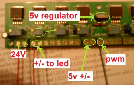
I can can leave the 5 volt regulator off and get 5 volts from somewhere else. Or you can use this to power another device. DO NOT connect multiple 5 volt supplies together.
so it get its 5V normally from the voltage regulater on the board
but I could also supply it with a external 5V but than I have to remove the 5V regulator.
so now the thing is, can I check if it is even getting 5V from the regulator, ore is something ellls wrong.
se at this time I dont even know if the driver, ore the code is wrong, so how can I check the driver ?
I cant reach Rob (thefishman65) so I'm stuck for over a week already with a room up side down.
I know there are some on here that have the same driver, could someon send me a pic showing there whires, so I know I'm right ore wrong.
se I have also seen a pic from this board that shows a whire from the 5v conector to a pwm,
http://www.reefcentral.com/forums/showpost.php?p=17221092&postcount=859
so before I start conecting things, and bracking the driver I need to make shore I'm ok
Attachments
Don't you need at least one more wire on that setup (based on pic)? Since you have 24V in to the board (like i have on my design) then one screw terminal is +24V to the +LED, another terminal is -LED going back to the CAT4101. Without this the circuit is incomplete.
not clear what you mean, there is a 24v + (red) and a - (white) and there is a + and - going to the LED and the PWM, what one do you mean is missing
terahz
1x10^12 Hz
Heads up to anyone planning to use my driver boards. There is a little problem with the analog dimming part. Apparently the chip supports a third dimming method (RTFDS) and switches to internal power source when there is a resistor (pot) from Iadj to GND (which there is on my board for the voltage divider 5V - 1.24V), so you can never shut off the LEDs (there is about 30mA current when 0 volts are passed). I'm thinking how to take care of that now. Just wanted to let you know.
I guess I can just skip the voltage divider but then there will be "only" about 64 dimming steps from an arduino...
If anyone has ideas I'm all eyes.
I guess I can just skip the voltage divider but then there will be "only" about 64 dimming steps from an arduino...
If anyone has ideas I'm all eyes.
terahz
1x10^12 Hz
Yeah, I don't like the 64 step idea anyway. I also found out that even if Iadj is grounded, there is 8mA through the LEDs. I've emailed NatSemi to see if this is the expected behavior. If it is, might have to put some transistor to switch the EN pin if the voltage is less than say 0.1V... Will wait for them to answer and will take it from there.
is there something wrong with the 5V regulator, ore its conections
is there something wrong with the 5V regulator, ore its conections
still locking for a solution to find out why I cant get things running. se http://www.reefcentral.com/forums/showpost.php?p=19203918&postcount=1869
so what I wonder now is, if even my driver boards are working.
as mentioned before, I know there are some here that know the boards, ore at least the cant 4101 chips, only thing is it appears, 90% of them are on holiday ore so,
anyhow.
I try of Corse things my selves as well. and going a bit more in detail, I hope some can point me to this question.
the CAT4101 driver boards are supplied with 24V, and the cat itself needs 5V, in order to drop the voltage from 24 to 5V a 5V regulator is installed on the driver board (specifically this one: on page 4 http://www.semic-shop.cz/fotky850/fotov/78xxAB_ST.pdf)
so locking at this, and on my board, there are 3 pins, a input (24V), aground and a output(5v)
now the question is, is I supply the 24V on my board, and everything is fine, I should be able to read the 24 and 5V of of the pins on the board, ore not ?when I put the multy meter on the pins, when the 24V is applied, I can measure 24V on the connections of the 24V to the board, but no 24V on the pins of the voltage regulator, nor can I measure the 5V.
so in fact I already wonder if the boards are even working ore not,
could someone give me some info on this (if I’m right with measuring the voltage regulator) because there might be something wrong here already, making it un necessary to lock even further
I still cant reach thefishman65 to go over all this, so depend on your input
thanks
Last edited:
Similar threads
- Replies
- 0
- Views
- 83
- Replies
- 6
- Views
- 851
- Replies
- 20
- Views
- 2K