Thanks, TheFishMan65. I've done something similar in other threads and I know how much work goes into it. Here are some things that I wrote down while doing my research. Some of it duplicates what you have, but much of it is new. Unfortunately, much of it is not credited since I had it for my own use:
How to install Meanwell ELN-60-48D
The AC wires that go into a plug dont matter which way.
The V+ goes to a + on the LED the - of that LED goes to the + of the next LED etc.
The - of the last LED in the string goes to the V- of the driver.
The two DIM signals go to your ALC dimming channel.
Set the dimming output of the ALC to max (+10V) then set the meanwell max current to what you want the LEDs to run at. DO NOT turn on the driver until you have turned the internal dim pot counter-clockwise all the way or you will blow the string when you turn it on the first time.
THEN adjust upwards. To measure the current properly you need a digital Multi Meter placed inline on the LED string to read the current.
To help clear it up. The driver you have has TWO ways to adjust the power that the LEDs are running at (actually three, but the third - voltage limiting - doesn't come into play when it's run as a constant current LED driver.)
First, there is the internal trimpot. Think of this as the max. limiter for current provided to the LEDs. The trimpot sets the max current (amps) your LEDs will run at. You adjust this internal pot simply by turning it with a screwdriver and reading the CURRENT (amps, not volts) on the output string, i.e. in series with the LEDs.
Second, there is the external dimming signal, connected to the external wires. This external circuit allows you to dim DOWN from the max current set by the internal pot. You control this function by providing a voltage signal to these wires, between zero and 10 volts. The LEDs aren't actually running at this voltage, it's merely a signal. The driver translates the signal into a percentage of the current set by the internal trimpot.
So, when your external signal source (ALC, whatever) is providing a 10v signal, your LEDs aren't running at 10v, they're running at 100% of the current limit set by the internal pot.
The internal pot is a set and forget kind of thing - you configure it when you install the system, and then you likely won't touch it again. Depending on your plans and which LEDs you're using, typical values might be between 700 and 1000mA.
The procedure Stu suggested above is 100% exactly what I would suggest. Turn the trimpot all the way down (counter clockwise). Wire everything up, with your external control signal set at 100% (i.e. 10v). Put a multimeter set to measure amps in series with the LEDs. (make sure it's well connected, you don't want loose connections!) Plug the whole thing in, and measure the current. Leaving your external signal set to 10v (100%), adjust the internal trimpot upwards until you get the current you want, which will be between 700 - 1000mA for most people. Then, unplug the driver, remove the multimeter from the circuit, close the circuit, and you're ready to go.
LED Quantity, spacing, lenses
Originally Posted by TheFishMan65
I think I remember reading that there was a recommendation of 1 LED for every 10 to 20 square inches. The above spacing would give 1 for every six inches. taqpol used 1.75 by 2. Lots of light in the middle (especially with lenses), but I little dark for what I think I want on the edges. So I will try and adjust my plans based what I have learned for taqpol.
In the past, I was suggesting people end up with between 10 - 20 square inches of tank surface area per LED. That's where the vast majority of "successful" medium-sized LED rigs have ended up, depending on drive current, livestock requirements, height, optics, LED model and bin, etc.
So, for instance, if you have a 120g tank, it has 48*24 = 1152 square inches of surface, so you might want 60 - 110 LEDs.
Lenses
Yes as mentioned above lenses can be use to increase PAR, but at the sacrifice of the edges. I think lenses should be reserved for controlling height (keeping the light in the tank as the fixture rises). Here are my opinions on height. NOTE: I held a single white XR-E (no lens) near the surface and had no shimmer I had to move it about 4-6 inches (IIRC) away before I got shimmer. So there is a minimum distance if you want shimmer (I do). Also personally I would always use at least 80 degree lenses.
80 degree - 4 to 20
60 degree - 20 to 36
8 degree - 36 - 48
Well let's start debating!
Those rough guidelines are probably about right. It's hard to give really specific suggestions because of all the variables, and not every type of LED has every width of optic available (i.e. there really aren't any 60 degree optics for XP-G that I'm aware of). I might cut your ranges a little as follows, for "average" depth tanks (say, 18").
80 degree: anything up to a foot
60 degree: 18"
40 degree: 24"
20 degree: 36"
anything smaller: on the ceiling!
As noted above though, concentrating the light with optics has other inherent effects besides the obvious one of increasing intensity and reducing spread. The spacing between your LEDs becomes a little more important as your optics get narrower, both from a coverage perspective and a "color separation" perspective. When you have wide optics or no optics, it doesn't matter that you are alternating blue and white LEDs every few inches (typically) because by the time the light hits the tank, it's "mixed" together well. With really tight optics, you can get an effect where shadows look blue on one side, and yellow on the other side - this is because the different colors of light are so laminar that they don't "mix" evenly.
And, of course, you can get the typically undesirable "shafts of light" effect if you use tight optics and big spacing between your LEDs. So, typically, as your optics get narrower, you are forced into a closer LED spacing to compensate for these effects, which COMPOUNDS the typical issues of using tight optics (less light spread and more intensity directly under the LEDs.) Effectively, if you want or need to use tight optics on a larger tank, you are FORCING yourself into a very high output light fixture, because you'll have to increase your LED count (decrease spacing) to get good coverage. The alternative if you really want a lower-output fixture is to use lower drive currents along with the closer spacing and tighter optics.
One final thought on optics that isn't brought up often. As stated above, tighter optics result in more laminar light. As you change from wider to tighter optics, your light behaves less like an MH and more like a laser. As this happens, we start to get some effects that may be considered desirable, but it's very possible for them to become overwhelming with very tight optics. Namely, shimmer and "contrast" in the sense of shadows becoming very, very well defined.
Shimmer is pretty much a "good" thing to most reefers, and you can control/influence it easily by changing the amount of turbulence on the surface of your tank. So it's a non-issue.
Level of contrast in the shadows might be considered a good thing, up to a point. As your optics get tighter, there is less "sideways" light in the tank, which means that corals/rock located in a shadow will get less and less light. Up to a point, IMHO, this can be very desirable - the sharply defined, dark shadows can look really cool. BUT, for people with lots of corals, it can be undesirable if taken TOO far, because lower branches on big colonies will be receiving very little light, which might cause growth problems or die-back for the coral. This can be somewhat avoided by letting your corals grow up in the LED-lit tank, and/or creative effects with LEDs.
Which brings me to my last thought for this post (I promise!). The above "dark shadow" issue could be easily thwarted if a few LEDs were angled with respect to the tank, instead of all of them pointing straight down. To date, 99% of LED builds have been BORING! The typical approach is to get a big heatsink and spread X number of LEDs evenly across it, then hang it above the tank. This gives a final result very similar to what you'd get with T5 and MH. A perfectly even and vertical distribution of light from edge to edge across the tank. LEDs let us BREAK FREE from that mold if we so desire! You can't bend a T5 lamp to get "angled" light at one end of the tank and vertical light at the other end. BUT that is easy to do with LEDs! Us reef folk seem happy to have actinic lights coming on before white lights as "sunrise" simulation. Imagine a tank where the "sunrise" actually involved a narrow shaft of light piercing the tank in a nearly horizontal fashion. The possibilities are endless! We can position individual LEDs, or small banks of LEDs, at different heights, angles, and positions to get some really cool effects. Time to think outside the box!
XP-G Optics: I ordered the 60 degree optics from etgtech.com for $1.25/pc plus shipping.
I don't believe they have them listed on the site so you will likely have to email
anna@etgtech.com.
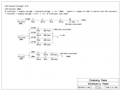
Series or Parallel
Fairly simple actually. With the same power supply, in this case for 4 LEDs with a forward voltage of 3.3v, of 15v.
The series circuit, uses less current draw from the power supply, and a single resistor.
The parallel circuit, uses a higher current draw from the power supply, and larger multiple resistors.
Another way to look at it, you need a larger voltage, lower amperage, power supply for series circuits. A smaller voltage, higher amperage power supply for parallel circuits. Assuming the same number of LEDs.
With power supplies, having less than the total forward voltage of all the LEDs, it is necessary to use a series/parallel circuit. In this particular case, the power supply is easy to come by, and the closest standard size resistor 120 ohms, is the exact size needed. The other circuits use the next closest higher resistor. (results in dimmer LED output, because less current will flow.
So from a design point of view, you design for the type circuit that will give the best results, in this case, although the series circuit is close enough, the series/parallel circuit with a 9 volt supply, will perform the best. (LED output wise, power is a secondary concern-- except for dissipation, depending on the size of the array)
See circuits below. If there are math errors, it is the calculators fault (it is an old TI-36X)
The greatest difference is seen in the total power (wattage) for the circuit.
----see attached diagram----
(kcress)
You should only have one driver for each string. Period.
Any other scheme risks all the LEDs as soon as one fails shorted.
Two stings in parallel will toast them all. Why?
If you are running two stings in parallel and each string is, for example, 700mA, your driver would need to put out 1400mA. Now if one LED shorts the driver will continue to drive 1400mA into the two stings. But the string with the shorted LED will have a different voltage requirement than the good remaining string. This causes what is termed as "current hogging". The good sting will either go dim or OFF completely while the bad string may have 1200mA running thru it. The remaining LEDS will fail in seconds.
Once the entire string with a short in it has blown or one of the LEDs fails OPEN the driver will then focus on driving the 1400mA thru the remaining good string. Every LED in that string will also fail within seconds in a domino effect.
One driver per string!
Drivers cost money.. How do you deal with this?
Two ways: The first is to string far more LEDs in a string. Using a 36V or 48V driver or at least 24V. 12V borders on the ridiculous.
48V/2.2V = 21 LEDs
36V/2.2V = 16 LEDs
24V/2.2V = 10 LEDs
Alternatively you could run strings in parallel but you would need to put a fuse in series with each string. As soon as an LED fails shorted that string would hog current, exceeding the fuse rating, and the fuse would blow. Promptly the full current would try to run thru the adjacent parallel strings and those fuses would also promptly blow. It would take some careful fuse selection however.
How to test forward voltage of individual LED's:
Wire them to a driver (you can do lots at once if you want). Run them at your target current. Read voltage across each one with a multimeter, by probing right at that LED's solder pads.
Really, the only trick to it is not blinding yourself. It helps if you have optics or an optic holder that leaves the pads exposed, because then you can easily look at the LED from the side without getting blinded.
(der_wille_zur_macht)
Parallel strings are not ideal in these applications, for a few reasons. First of all, if there are any tiny differences in characteristics in your various LEDs, you'll have inconsistent performance. If you have one string that ends up requiring 10.3v to drive at 700mA, and another string that requires 10.5v to be driven to 700mA, then the driver will end up over driving one string and under driving the other. Since even a small variation in voltage can lead to huge variations in light ouput, this might mean poor performance from some LEDs. In practice, I've seen 3 - 4% variation in drive voltage to achieve a target drive current from LED to LED (even in the same bin) which is enough to make me worry about performance in parallel applications.
ie If you were to get a 1400ma driver, running two parrallel strings at 700ma. From what I gathered when you were discouraging people from doing this in the early parts of this thread, the concern is if one led blows. 1400ma would then start running through the other string, cause the entire string to blow because of one led.
So, what I am thinking is with the led's (I am looking at the common standard of the Cree XR-E RB, and now for whites the Cree XP-G) being maxed out at 1000ma, protecting both strings with a 1 amp fuse would prevent the entire 1.4 amps from being diverted to a single string and over powering them. Then worse case scenario, the max that would go through anything would only be the leds max.
A: (der_will_zur_macht) Daniel, fusing the parallel strings would prevent failure, but it leads to some other (potential) issues:
1) If the LEDs in one string have a different total forward voltage at a given current than the LEDs in the other string, they won't balance out well. This would be especially true if you mixed different colors/types of LEDs on the same driver. I'd want to carefully "bin" the LEDs I was using (set up a test station where you could drive a single LED for a few seconds to record it's voltage at a given current) to avoid this.
2) As you get more LEDs on a driver, you start to lose control resolution. Maybe this isn't an issue on a very large tank, but on a smaller tank, if you had drivers doing 12, or 24 LEDs each (for example) you quickly lose resolution to the point that it would be hard to implement the sort of control people are starting to show interest in. For an extreme example, I have a nano rig with 16 LEDs run at very low current. This is two of my DIY drivers, 8 LEDs each. A driver capable of doing all 16 wouldn't even let me dim blue and white separately.
From the sounds of your posts, neither of these would be huge stumbling blocks for you, but I wanted to point them out in case others were following along.
Binning LED's, adding Fuses (Kress)
Originally Posted by laverda
Kcress It that is true how many parallel strings of LEDs could you reliably run on one Meanwell? Even if it was just two it would save substantial cost on a large system. If it was 4 it would would also make controlling with an Aquacontroller much easier for me.
You could theoretically run 4 strings of 48/3.5 = 13 LEDs.
Or 52 total.
You would be limited to 1.3A / 4 = 325mA per string.
To do it right though you'd need to do some additional work.
It would consist of some detailed meter work.
You would set up a string on a Mean Well and set the string current to 325mA using an ammeter.
Turn it on and wait until the string is warmed up. As you wait, use a Sharpie to number every one of them. Once warm measure the voltage across each one and write it down in a numerical table.
Do this for all 52.
Now take this table and mix and match the values to end up with the same total voltage in each string. You could do this many different ways. Use, say, the highest 5 with the lowest 6 if that works. Or just match across one low one in each string then the next higher one in the next string, etc, etc.
Once you have them grouped build your 4 strings.
You need to build the strings normally BUT you need to add fuses in each string.
Something like a 375mA fuse. Digikey F1504-ND in a holder F1467-ND.
Now when a LED opens or one shorts the fuse will open protecting the rest of the string.
Note that if any fuse opens they will all open, so keep spares.
If you can't pull this off as described, don't run parallel strings.
(der_will_zur_macht)
Skeptic, it's an easy problem to solve. Set up a "test station" with a constant current driver that can power a few LEDs at a time at some reasonable current, while allowing you to probe each individual LED with a multimeter. Turn the test array on, test the voltage drop across each LED, and write them all down. Then, arrange your LEDs into groups such that the total voltage drop for all groups is as close as possible. That's what I meant about "binning" your own LEDs. It should take an hour or two max, and it's cheap insurance if you're running parallel strings.
.2v CAN be quite significant (like 100mA!!!), but I'm not sure you'd see variation that high unless you randomly stacked things up in the worst possible way.
LED Specs
Cree XR-E Royal Blue
Color: Royal Blue
Dominant Wavelength Range (nm): 450 "“ 465
Max Current (mA): 1000
Viewing Angle (°): 100
Standard Min. Flux @ 350 mA: 425 mW, 350 mW
Cree XP-G Cool White
White: Cool
CCT (K): 8,300 "“ 5,000
Max Current (mA): 1500
Viewing Angle (°): 125
Standard Min. Flux @ 350 mA: 139 lm, 130 lm, 122 lm, 114 lm
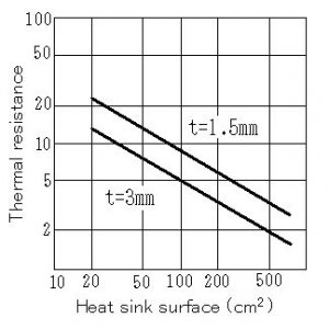
Heatsink Size (lynxvs)
I've posted this before I think but it might be helpful. I use just a flat plate of aluminum as my heat sink. I did some calculations below to justify heat sink size. I attach a PCB directly to the plate using screws.
Max Junction Temp = 150° C
Power of Single LED = 3.4 Forward Voltage X 700 mA = 2.38 W
Ambient Temp = 70° C ( A SWAG)
Thermal Resistance between Junction â€"œ Case (From Data Sheet) = 10° C/W
Thermal Resistance between Junction and PCB (From Rebel application note) = 7° C/W
Total Thermal Resistance = 10 + 7 = 17° C/W
Total Thermal Resistance between Junction and ambient air = (150 â€"œ 70)/ 2.38 = 33.61 ° C/W
Thermal resistance between Case and Ambient air = 33.61 â€"œ 17 = 16.61 ° C/W
The amount of heat dissipation that can be achieved with a flat plate of aluminum is indicated below.
---see attached diagram---
Using a 3mm plate looks about 20 cm^2 per LED converting to inches is equal to 3.1 in^2 * 50 LEDs = 155 in^2 The plate I am using is 24 X 7.25 = 174 in^2 not sure if you can count both sides of plate as surface area… I also have two cooling fans to help…
Grounding
Originally Posted by 100%hydrophylic
what do i do with the extra green wire on the power cord? just leave it?
Crimp ring terminals on them and screw them to the heatsink. Do the same with the power cord's ground wire. The official way requires they all be under the same screw but you will get the same effect if they are all hooked the same chunk of metal.
Partial Summary
First, I don't think there is any difference between the cool white and royal blue (XR-E). Both are 3W, have a forward voltage of ~3.6v, and take a max current of 1000mA. However, I've read that the royal blue (and white to a lesser extent) are best run at a slightly lower current. Say 700mA. This extends the life of both types of LED with only a slight decrease in light output. This means that both colors could be on the same driver. But, most people don't so they can dimm them by color and turn them on at different times to simulate sunrise/sunset. I'll try and get confirmation on this.
The Meanwell, specifically that in the group buy ELN-60-48P, is a line voltage constant current source. It provides a constant 1.3A (-25%,+3%) to the LED load on it. It can handle up to 48V max on the load. And the P means it is externally dimmable with an analog signal. The line voltage part means it just plugs into the wall (90 - 240v), no additional power supply is needed. The max constant current is changeable by an internal potentiometer -25% or +3%. This means it can output from 1A to 1.4A or so.
LEDs have a current requirement and a forward voltage. For the Cree XR-E that is ~1A and 3.6v (on average). In series, voltage adds and current is the same. Thus, the Meanwell can power up to 13 XR-E in series at 1A (with the max current at -25%).
It can also run two parallel strings of 13 LEDs at 700mA per string with the max current set to +3%. Current divides in parallel so a total of 1.4A is being provided but each string gets 700mA.
A word of caution with parallel strings of LEDs. This is a recipe for disaster. If you aren't comfortable building this next item, don't run LED strings in parallel. What happens is if one LED in one string dies, then that string shorts and all of the current is sent through the other string. This either kills part or all of the LEDs in the other string or it severely limits the life of the LEDs in the second string. The higher current will work but it will also heat up the LEDs a lot. That is how they die.
But, you can do parallel strings as long as you build in a current mirror. Evil66 found and posted this in the Meanwell thread on nano-reef. Basically it forces the same current in both strands. If one strand shorts then it shorts the other strand too. The Meanwell thread:circumventing the filters is generally frowned upon
CJ
")