DIY LEDs - The write-up

Status
Not open for further replies.
I just soldered, wired, and screwed down all of my leds. I used rubber washers with the screws to prevent shorts. I'm sure there has to be at least one short somewhere.
I don't know how to use a voltage meter, but I read that you guys use a pair of AA batteries and test every led? Could someone explain the procedure of testing with batteries? Will this show a short (grounding to the heastsink)
I was also going to do the below following steps after I'm sure there are no shorts in the system. FYI I have Meanwell ELN 60 48 D's and a digital aquatics ALC (not hooked up yet). Using a 9 volt battery for now as the driver signal.

From DWZM on another build.
Take the last wire from the "-" pad on the last
LED, and connect it (securely, with alligator clips or some other
solid method) to the "+" lead on the multimeter. Then, connect the
"-" lead on the multimeter to the "-" lead from the driver. The
meter is now in series with the LED string.
Turn the meter on, then plug in the LED driver and check the reading on
the meter.
I did all of this (i did not power up driver yet-just a dry run) but what about the red wire from the driver?
I have the multi meter red probe plugged into the non-fused 10 amp socket.
Do I set the multimeter dial to volts while adjusting the meanwell pot to set the max amps to 700mah?
Sorry for the length of these questions.
Thanks,
Wade
 
Last edited:
Frode,

I don't think anyone can answer if you will have heat problems. .18 is kind of close, but with good ventialation probably ok. I am also not clear on the specifics of your heat sink.

Thanks for your replay FishMan65,

Ventilating will be a challange when building my LED bars into the ATI fixture.
But I will figure that out.

The only specifics of the cooling bars I have:

- Profile material: Aluminium (anodized)
- Profile height: 20mm
- Profile width: 35mm
- Weight/m: ~1000g


As long as somenone can say the risks are not to high then I'll try :twitch:
 
Some more thought on rebuilding my ATI T5 fixture.

The most simple way to rebuild the ATI fixture is placing the coolings bars for the LED's above and between the T5 lamps (see attached drawing, and picture fo the cooling bar - upside down). The T5 are spaced 2 cm under the housing. The cooling bars are 2 cm thick. As the T5 are 'covered' by reflectors, I think the cooling bars will not be effected by the heat of the T5 lamps to much. I will even have space to place lenses on the LED's if I want to.

The air flow in the ATI fixture is now as follows: On the long sides there is a gap of 2 mm between the acrylic cover and the housing, in the bottom of the housing there are holes on one side, at the foot of each T5-lamp.
At the top of the housig there is one small fan in the middle.

So the air will go into the fixture, partialy passing the T5 lamps, then entering the housing it will pass the evsa and then exiting through the center.
This will not be enough for cooling the LED bars I think.

So I plan to drill some holes in the bottom of the housing on each side of the LED-bars. And put two fans in the housing right above each LED bar.

But why do I want such small spacing between the LEDs?
Well, fact is I now have placed 16 LED's on each bar (I'll loose one on each bar by shorting them from 100 to 90 cm).
I am loosing 2 x T5 but don't want to loose light... so I want to add more LEDs. Drilled all them holes and tapped them :fun4: Do'n't want to redo that all. And the way I drilled the holes now, I can just fit in a LED between each two LED's ;) So then I come to a total of 29 LED's on 90 cm cooling bar.
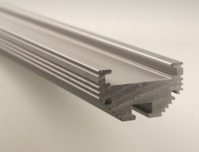
But maybe it's to much? I still have 10 CREE XP-G waiting on a shelf. Maybe I should start with placing only those in between. That would make 21 LED's on each bar, center to center 4,5 cm (1,8").

And another option to gain more light is running them at 1000 mA...just need to add some more PS ...

I'll have to much white in the LED's I think (10 x CREE XP-G R5, 20 x CREE XR-E white, 12 x CREE XR-E Royal Blue) , but I can 'play' with the T5 lamps to adjust the totall spectrum of the fixture.

Well, I'm all in for your opinions :thumbsup:
 

Attachments

  • LT-1512-1237978925.jpg
    LT-1512-1237978925.jpg
    16.6 KB · Views: 8
  • ATI-t5-led.gif
    ATI-t5-led.gif
    11.1 KB · Views: 6
How do you test for shorts if the screws are touching the pads and grounding out in the heatsinks?
If there is a short like this will I blow the leds in the string if I power up the driver?
Wade
 
Resistance measured from a metal screw threaded into a metal heatsink should be very SMALL. What you want to test for is resistance from each of the solder pads on the LED star to the heatsink. You should get NO response, i.e. an open circuit, as if you were holding the meter probes in midair not touching anything. If you DO get a response, then you have a short.
 
Not normally will you blow the LEDs in this case. Depends on a lot of things.

Test for shorts with an ohm meter with the power off. 'Ohms 200' scale or 'continuity' from each wired pad to the heat sink. If one is less than an ohm you have a problem.


Whoa..
2iaxvrt.gif
Missed this whole page of answers. I pressed the "Go to last read thread".
2hgeq95.gif
 
Last edited:
kcress,

Maybe you are replying like I am or maybe I am misunderstanding. From wired pad to heat sink better be way more than an ohm as DWZM pointed out.
 
I have LIGHT!
82310LightsAll.jpg


Quick Disclaimer!
All of these pictures were taken with my wife's P&S and my SLR is still in the shop. As such this does not represent the true color at all. That being said, I am very happy with adding two neutral whites per string of twelve cool whites and in the future I might have even gone more drastic with four or six neutral whites per twelve whites. The moment I get my SLR back I will try and take some true color photos.


My fixture has five fixtures of 24 LEDs a piece, twelve blues and twelve whites, controlled independently for ten channels of LEDs. The entire thing will be controlled by an Arduino Mega to ramp up and ramp down the LEDs from the left of the tank to the right to simulate sunrise and sunset. All the fixtures are mounted 12.5" above the tank (14.5" above the water) and the four outside fixtures have 80 degree optics on the outside rows and 60 degree optics on the two inside rows of LEDs. The entire center fixture has no optics, this is because I did not plan to have many high light corals in the middle valley of the tank and also for better coverage. Coverage is definitely not an issue, but PAR down the middle is, so I'll probably pop on at least 80 degree optics in the near future.

Here are some pictures to show what the coverage looks like based on individual fixtures. The far left and far right are interesting because I have them angled into the tank.

Far Left
82310LightsMidLeft.jpg


Middle Left
82310LightsMidLeft.jpg


Center
82310LightsCenter.jpg


Middle Right
82310LightsMidRight.jpg


Far Right
82310LightsRight.jpg


Some people think you can use high power LEDS as moonlights. Maybe if you could just run a single one, but when I tried my smallest possible amount of the twelve center white LEDs with a PWM signal of 1 (out of 0-255) I thought it was still much too bright to be used as a moonlight.
82310LightsMoon.jpg


It is cool that the DIY drivers I used dim all the way down to 1 as it is a neat effect. Here are all the fixtures at 1 of 255.
82310LightsOne.jpg


And now what everyones been waiting for, the PAR numbers! Thanks go out to ReefEnabler for letting me borrow his meter!
82310LightsFTS.jpg


Numbers in red are the PAR numbers at the very top of the water. Numbers in yellow correspond to the reading taken directly in front of a coral or outcropping of rock. Numbers in black are on the sand bed. For reference, the tank is 220 gallons, 72"x30"x24" tall.

As you can see, the PAR is definitely lacking in the central area. I'll test again after I throw some optics on. Other than that PAR drops off significantly towards the front and back of the tank (it is 30" wide), but that shouldn't be too much of a problem since I don't have any rockwork there to grow corals on. Going by the rule of thumb of 200 PAR for SPS corals I should be able to grow them almost anywhere in the tank, including the sand bed in some areas.
 
Hello there,

It has been a while since I posted my DIY LED project http://www.reefcentral.com/forums/showpost.php?p=17101317&postcount=3509

Soon I will be upgrading my tank to a 600 L corner tank.

I am planning to only light the center part of this tank. My ATI 6 x 39W T5 Sun Power fixture will fit just perfect.

My plan is to rebuild this T5 fixture. Loosing 2 x T5 and replacing them with my DIY LED bars. As you can see in my former posting, I placed 16 LEDs on a 100 cm (39,4") aluminium cooling bar, approx 6 cm (2,4") spacing between the LED's from center to center. I will have to shorten these bars to 90 cm (35,4") to fit them in the T5 fixture.

And I want add more LEDs (CREE XP-G).

My question: will I get in to trouble when I when put 29 LED's on each 90 cm Bar. Spacing of the LED's will be 3 cm (1,18") center to center. Running them at 700mA ?

A lot is going to depend on what your mounting them to and the current you run them at. Your description of cooling bar does give much to go on. From my experience, I think it will get way to hot, if it is just a flat bar. Even U channel will get to hot enclosed in the fixture, unless you vent it much better then the way the come.
 
kcress,

Maybe you are replying like I am or maybe I am misunderstanding. From wired pad to heat sink better be way more than an ohm as DWZM pointed out.

Oh yeah 4 shore.. I am just pointing out that a shorted connection will be around 1 ohm depending on the probe tips, surface contamination, and meter quality.

******************************************

Taqpol.. R e a l l y n i c e !! :beer:

The 1 of 255 is cool.

Thanks for the effort of PARing it too!
 
noob alert!!!!


I'm gonna bug ya'll with some questions.

I've posted before about a 180gl. I was planning, but I got a really good deal on a 135gl. so thats what my tank is gonna be.

Its 72in by 25in by 18in. I wanna be able to (eventually) keep any darn thing I want to in it (as my experience warrants).

I was looking at that really cool Vertex illuminata......$4560...Aint happening!!!

So I'm looking into DIYing my own.

My question is: How many, of what colors would the experts here suggest I use. I started out doubling the OP. But my inexperience tells me I need guidance.

I can follow the directions on building them, thanks to the OP's concise instructions. Just having a bit of trouble with the amount, pattern and placement of them!!

Oh Yeah.....this is gonna be a peninsula tank also.....if that makes any difference.

Thanks ahead of time!!!
 
I'm still waiting for somebody to verify the below steps-I feel like it is missing one thing.
DWZM gave this advice to someone else on testing/adjusting the amperage of a led string.
Take the last wire from the "-" pad on the last
LED, and connect it (securely, with alligator clips or some other
solid method) to the "+" lead on the multimeter. Then, connect the
"-" lead on the multimeter to the "-" lead from the driver. The
meter is now in series with the LED string.
Turn the meter on, then plug in the LED driver and check the reading on
the meter.
I did all of this (i did not power up driver yet-just a test run) What about the red wire from the driver?
Sorry to keep bugging you guys about this- I feel really dumb.
Wade
 
Status
Not open for further replies.
Back
Top