You are using an out of date browser. It may not display this or other websites correctly.
You should upgrade or use an alternative browser.
You should upgrade or use an alternative browser.
DIY'ing a controller for the Maxspect Gyre
- Thread starter dartier
- Start date
For the Gyre, the connectors are a different size than a Jebao. To purchase the matching connector off eBay, I held the original up to the monitor and used the relationship between the length and ring diameter.
There are sellers on ebay that do sell the right sized connector. The really critical dimensions re the pin sizes and spacing. The keyway on the orinal connector is a slot but I think you can use one the has a flat (cut out) because the pump side is fits. You will need to confirm that.
For the record I am never likely to finish this project even though I have all the parts. I am starting a new build and getting the Gyre controlled is no longer on the top off my list.
Yup. That too.It is worth noting that there is now a controller that is available for purchase. Icecap gyre
Dennis
Hi everybody ! :wave:
I'm trying to control my Gyres using my Arduino. Generate the 6 signals which drive the gate of the controller's Mosfet seems to be a little difficult, especially for the N-Channel side. For the P-Channel, it was easy:

So, I have tried to power the Maxspect's controller with a variable power supply and... it works, between 9 and 24V, the Gyre runs perfectly, its speed depending of the voltage. :bounce3:
So, what we only have to do is to convert 5V PWM to 9-24V DC. I just have to check if, running it undervoltage, could damaged the motor of the pump ?
I'm trying to control my Gyres using my Arduino. Generate the 6 signals which drive the gate of the controller's Mosfet seems to be a little difficult, especially for the N-Channel side. For the P-Channel, it was easy:
So, I have tried to power the Maxspect's controller with a variable power supply and... it works, between 9 and 24V, the Gyre runs perfectly, its speed depending of the voltage. :bounce3:
So, what we only have to do is to convert 5V PWM to 9-24V DC. I just have to check if, running it undervoltage, could damaged the motor of the pump ?
LostShoopuf
New member
Hi everybody ! :wave:
So, what we only have to do is to convert 5V PWM to 9-24V DC. I just have to check if, running it undervoltage, could damaged the motor of the pump ?
I'll admit I haven't looked at the Gyre's specs yet, but have you looked into using an H-bridge for driving the pump?
LostShoopuf
New member
Gyre's motor is brushless with 3 phases, I think that the H-bridge will not work with it")
Single H-bridge, no.
3 half H-bridges, one for each channel, yes, assisting in isolating your control circuitry from the power load from the motor.
LostShoopuf
New member
The main difficulty will be to generate the signals of the seconds channels, I don't know how to do it
Let me get home from work and see if I can come up with a write up on how to accomplish it.
Basically you're no longer treating the signals as a PWM where the pulse width controls the speed, but the toggling between the 6 pins does it. Faster you go, the faster you toggle between the pins. In some ways it may be even easier to implement than multiple PWM signals.
Wally.B
Active member
Me again.
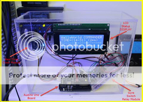
Thought I give an update on the DIY (Ardiuno) - Gyre Mod Controller.
Some improvements (Real Time Scheduler with Battery-BackupOnClock, and a LCD Display).
With Audino, I could hook up to Apex (0-10V) VDM and read voltage so it could be integrated, or standalone or combo.
However I'm leaning on Standalone since no spare VDM ports on my Apex, and this unit could control motor both directions.
DIY - Gyre Pump Controller (Controller)
Now that I have a modular unit, I'm going to tackle the Speed Control (Encoder), and if I figure it out, if may be less work then figuring out a Motor Controller.
However I do respect everyone trying to figure out the Motor Control. I love challenges too. All the best.
(Has anyone built a working Gyre Pump MOTOR Controller yet?). I can still go either way with the unit I have.
Last edited:
d0ughb0y
Active member
Hi everybody ! :wave:
I'm trying to control my Gyres using my Arduino. Generate the 6 signals which drive the gate of the controller's Mosfet seems to be a little difficult, especially for the N-Channel side. For the P-Channel, it was easy:
So, I have tried to power the Maxspect's controller with a variable power supply and... it works, between 9 and 24V, the Gyre runs perfectly, its speed depending of the voltage. :bounce3:
So, what we only have to do is to convert 5V PWM to 9-24V DC. I just have to check if, running it undervoltage, could damaged the motor of the pump ?
did you try looking at the waveform of the gyre controller signal to the pump? Doesn't the connector have only 3 pins? if so, then it can't be sending the 3 phase signal. Would it still be 24v, gnd and pwm? what is the pwm frequency and how would it control direction and speed?
Similar threads
- Replies
- 3
- Views
- 233
- Replies
- 2
- Views
- 215