Electrical Help - Breaker Panel

I must have missed something as I'm skimming through this post but...
why so many wires when you only have 2 circuits? you don't pull full runs for each outlet unless each outlet is on its own circuit..
You should have no more than 2 hots and 2 neutrals + grounds in any pipe/box for 2 circuits..no matter how many outlets you have..
 
HI Paul,

I wasn't planning to silicone but read some other people have done that. I do have normal pvc primer/glue that we use on plumbing the tanks too - so that would be fine. On a side note - I'm having a hard time finding the PVC junction box with holes already in it. All I see are the square ones with no holes (looking at lowes).

I didn't see any junction boxes that had the holes in them already. The tubing I am using 3/4". All I saw (at lowes) was the 4x4x2 and 6x6x4 I believe - just a box with no holes, which is why I mentioned drilling.

As to why there are so many wires - each outlet is an independent GFI so if one trips, the others stay on and the whole circuit doesn't come to halt. It's the reason for this job in the first place.

Oops - one last thing - can you please explain the math for the box-fill rules. Did I do that correctly?

3 hots
3 neutrals
3 grounds (all grounds count as 1)

+

1 hot romex
1 neutral romex
1 ground romex (counted as 1 with the TTHN wires).
-----------------------------------------------------
Total is:

4 hots
4 neutrals
+1 for ground

9 * 2 (#14 gauge) = 18 CU in. needed - correct?
 
Last edited:
As to why there are so many wires - each outlet is an independent GFI so if one trips, the others stay on and the whole circuit doesn't come to halt. It's the reason for this job in the first place.

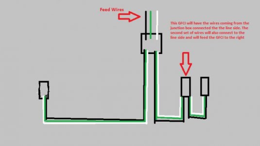
You can still wire it that way and eliminate a set of wires. One set runs to the outlet to the far left in the picture. The second set runs to the middle outlet box. Then run from the LINE connection on the GFCI to the next GFCI outlet on the far right. They will still act independently and it will save you some wire and space in the boxes/conduit.
 
You can still wire it that way and eliminate a set of wires. One set runs to the outlet to the far left in the picture. The second set runs to the middle outlet box. Then run from the LINE connection on the GFCI to the next GFCI outlet on the far right. They will still act independently and it will save you some wire and space in the boxes/conduit.

Ahh - ok I will need a diagram for this. I work better visually. So instead of 4 wires in each wire-nut there would be 3 - and the last outlet on the right would be connected via the LINE side.
 
If you can only get the boxes with no holes you need a 1 1/8" hole saw to cut the holes in the box for the 3/4 conduits. Then in Lowes you buy the threaded fittings that you glue on the ends of the PVC pipe. It is just a threaded piece on one end and a female piece on the other end that slips over the conduit. (3/4" threaded male adapter) Then you use that conduit just as if it was threaded. You put the threaded part in the hole you drilled and use a 3/4" locknut on it. You can also use plumbing parts as they are the same only plumbing parts are white and electrical parts are gray
 
Here is a diagram.
 

Attachments

  • gfci.jpg
    gfci.jpg
    22.2 KB · Views: 7
They sell boxes with those holes already in them like that, but maybe Canada doesn't stock them.
 
You can still wire it that way and eliminate a set of wires. One set runs to the outlet to the far left in the picture. The second set runs to the middle outlet box. Then run from the LINE connection on the GFCI to the next GFCI outlet on the far right. They will still act independently and it will save you some wire and space in the boxes/conduit.

If I was to do it this way - is it to code/legal/safe to have 2 wires under the same screw? I would prefer to secure the wire underneath the screw as opposed to simply putting it in the back of the GFI outlet.

If two wires are used from the line side - would it be better in this case to use the back-connection slide-ins as opposed to the screws?
 
I have another question about determining the number of conductors and devices (when calculating box-fill limits).

It states that every conductor is counted as 1 - and all grounds are counted as 1 together.

In my case, I have 8 conductors (3 outlets plus romex, for 4 hot/neutral) and the grounds, for a total of 9.

9 * 2 (14 gauge) = 18.


I just wanted to clarify this next point. I see that you also have to take into account switches or outlets into the calculation - and for every switch/outlet the number of CU. IN. increases.

So my question is this. Do you include the # of outlet/switches in the box fill limit ONLY if you are pig-tailing in the same box as an outlet?

Anotherwords - since the outlets themselves are not in the junction box, I do NOT have to include them in my box-fill calculations. This is because the junction box only has wires in it - not outlets.

Correct?
 
Another question....

I bought a 3 pack of GFCI outlets that say 15 AMPS on the box.

When I look at the receptacle itself, it says this on it:

GFCI Class A 20A., 125V., 60Hz / 15A Receptacle

It was this 3 pack from Pass & Seymour/Legrand

This confused me. Why does it say 15 amps yet "20A" as well? I don't want to install a 20 amp outlet on a 15 amp circuit.
 
Last edited:
If I was to do it this way - is it to code/legal/safe to have 2 wires under the same screw?

No, it is not legal. You have to either put one wire on each screw or splice the wires together and bring out a short pigtail for the outlet.
For the amount of fill in a box, that gets very complicated as the size of the conductors, size of the box, number of splices and devices all are in the calculation as well as if it is new work or rewired work. If you want to get into legalities (which I don't as I am retired) the current carrying capacities of those conductors must be downgraded depending on how many of them you have in each conduit. So if you have 5 conductors in a certain size conduit and they are normally allowed to carry 20 amps each, they may only be allowed to carry 14 amps because of conduit fill.
We rarely get involved in fill size for small boxes because if we did, almost no boxes would be legal. We figure that normally in large installations with much heavier conductors. Some electrical boxes can be almost as large as your house.
But to figure out exactly what you need to be 100% legal I would have top have my code book in front of me, or at least a Canadian code book and I purposely never look at it or in it's direction since I retired.
 
Thank you Paul. I went ahead and wired the outlets with single wires. All connections were done on the LINE of each outlet.

Here I left enough room (from what I read) for wires to be pulled out if needed:

11635731666_821ff8b19b_b.jpg


This is how I wired the outlets. I had some troubles with the screw connections, so decided to do the back-fitting for the hot/neutral. They are very snug and are not going anywhere.

11634958045_31603af4ca_b.jpg


And the somewhat finished (not showing left side outlet) result.

Red - hot, white - neutral, black - ground:

11635195123_330677d298_b.jpg


Could someone please explain the GFCI outlet information? If it's a 15 amp outlet, why does it have this written on it (the 20A., part):

GFCI Class A 20A., 125V., 60Hz / 15A Receptacle
 
Last edited:
Thank you Paul. I went ahead and wired the outlets with single wires. All connections were done on the LINE of each outlet.

Here I left enough room (from what I read) for wires to be pulled out if needed:


This is how I wired the outlets. I had some troubles with the screw connections, so decided to do the back-fitting for the hot/neutral. They are very snug and are not going anywhere.


And the somewhat finished (not showing left side outlet) result.

Red - hot, white - neutral, black - ground:

Could someone please explain the GFCI outlet information? If it's a 15 amp outlet, why does it have this written on it (the 20A., part):

GFCI Class A 20A., 125V., 60Hz / 15A Receptacle

It means the receptacle is approved for use on a 20 amp circuit but is still only a 15 amp receptacle.

If you were so concerned with code why did you use black wire for the ground?
 
pvc conduit is not allowed indoors for the reason that if catches on fire will leave a very toxic fumes.....also your ground black wire should have some green tape and should terminate with some type of sta,kon terminal...a stranded wire will eventually..get loose on the ground terminal...those type of terminals are for solid 14 gauge wire
 
It means the receptacle is approved for use on a 20 amp circuit but is still only a 15 amp receptacle.

If you were so concerned with code why did you use black wire for the ground?

I had looked for the green wire but could not find one anywhere. Hmmm that is a good point though. It was my understanding that red can be hot and black as ground when green is not available. I'll have to check now...
 
pvc conduit is not allowed indoors for the reason that if catches on fire will leave a very toxic fumes.....also your ground black wire should have some green tape and should terminate with some type of sta,kon terminal...a stranded wire will eventually..get loose on the ground terminal...those type of terminals are for solid 14 gauge wire

I will look into this sta-kon terminal. I am not familiar with it. I will go back to the store tomorrow and look for the solid wire. Is not PVC used in plumbing in the house too? Wouldn't that burn just the same if a fire occurred? Can you please point where in the Ontario code it is not allowed?
 
I will look into this sta-kon terminal. I am not familiar with it. I will go back to the store tomorrow and look for the solid wire. Is not PVC used in plumbing in the house too? Wouldn't that burn just the same if a fire occurred? Can you please point where in the Ontario code it is not allowed?

Red hot can be used but black for ground/negative is usually for a DC application .
 
Last edited:
Well... this is why I am posting on here to make sure it's done correctly. Can someone tell me if stranded wire can be used for connections in the back of an outlet? Ie) Do I need to remove the white neutral wire I connected?

Is the solid wire only to be used around screw-terminals? What disadvantage does the stranded wire have if connected via the slot at the back of an outlet... vs the screw portion?

I am going to find solid green wire to use around the green screws and then replace the red-hot with a black wire.

Do all 3 need to be solid or only the wire that goes around the screw?
 
I can only say that stranded wire is used in places where high vibration is expected.Im no electrician but in my experience around houses and boats, I have not found much in the way of solid wire on a boat or much in the way of stranded in a house. Slot vs screw in the back of the outlet doesnt matter for functionality. The screw connection may be easier to disconnect later. I would use all solid wire in this application.
 
I'm not familiar with the CEC, although I quickly looked up the colour coding and didn't see black being allowable for a ground. The code will often have exemptions in other areas and localities will alter the code also so YMMV. No person here, outside of a local-to-you electrician possibly, can tell you what is compliant at your house in Ontario. Most here will tell you what is safe and general good practice.

I know stranded wire can be used on screw connections here, although many frown upon it. If the rear terminals utilize a compression connection that is tightened via the screw terminal then they are fine for stranded wire here as well. Spring connections are not as those connections are marked for solid wire only.
 
Back
Top