LED Current Mirror

Hello - I am researching an LED build for my impending 180. I have decided parallel is the way I want to go. In reading up, you have to balance the strings. I've read adding/removing LEDs is one way to do this. I then thought there must be a more "automatted" way.

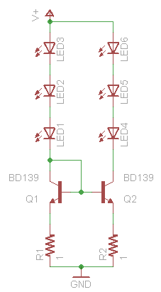
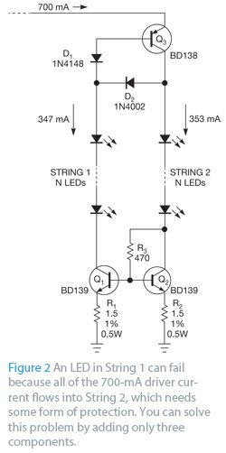
So, in searching I found this article on a current mirror circuit with LED that will balance the string and offer protection against over current:

http://www.ledsmagazine.com/features/6/2/2

Looks like with a couple transistors and resistors you can ensure the current down each string is close to the same.

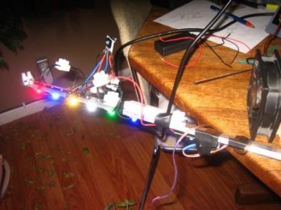
Note that I am no expert and stumbled upon this. I do plan on bread boarding it to see how well it works. I can't answer questions due to my lack of expertise and don't feel qualified.

I only share this because I didn't find it in my reef central searches. I also felt it was worth sharing, if for no other reason, than to share the concept or idea. (Could also be no one uses it because it doesn't work in our applications etc). Hopefully others will find this useful.

Diagram from ledmagazine.com
picture.php
 
Last edited:
If I were running a factory that was churning LED arrays out on an automated production line, something like that might be desirable. For a beginning electronics hobbyist who's soldering the array on his workbench at home, balancing the strings "manually" by measuring current and rearranging as required is probably less effort, cheaper, less confusing, and just as (if not more) effective.
 
I dont like relying on fuses, just like check valves they are nice but you never really know if they will work in the end.
 
Fuses seem to me as the most simple way to protect parallel strings.
And and imho the most simple solution is often the best way to go.
But you are right, if a fuse doesn't do its job...you risk a lot off damage.
 
I dont like relying on fuses, just like check valves they are nice but you never really know if they will work in the end.

Has anyone on here ever had the commonly-used style of fuse NOT work? Do you have any basis for your nervousness?

Not trying to be rude, just trying to understand. I've never heard someone say something like this before.
 
I plan on using fuses regardless if I do the current mirror when I build it.
Later on down the road if a replace an led or otherwise change the strings, I like the thought of having it balance itself.

I'm no expert but am comfortable with transistors (at least in this application)

With all the reading one does before a build I think most novices could do it with ease.

The cost of adding this is neglible when compared to the 4 figures I have to layout in LEDs!
 
Last edited:
If the appropriate fuses are used I can assure you they work quite well. A friend of mine recently went through 5 sets (30 fuses) while trying to figure out a driver issue. Not a single led lost out of 72.
 
If the appropriate fuses are used I can assure you they work quite well. A friend of mine recently went through 5 sets (30 fuses) while trying to figure out a driver issue. Not a single led lost out of 72.

I think we can say he's properly tested the fuse aspect :) Moral of the story - Fuse it or lose it!
 
Has anyone on here ever had the commonly-used style of fuse NOT work? Do you have any basis for your nervousness?

Not trying to be rude, just trying to understand. I've never heard someone say something like this before.


I have never heard of them either saving or failing, which means I have no bias what so ever toward them. I just know LEDs tend to fail faster then even quick blow fuses. And this seems like a minimal effort to add alot of protection to the system.
 
I have never heard of them either saving or failing, which means I have no bias what so ever toward them. I just know LEDs tend to fail faster then even quick blow fuses. And this seems like a minimal effort to add alot of protection to the system.

I'm not sure I understand this. You've never heard of them protecting or failing but you know leds fail faster? The fast blow fuses work. I know of at least 2 people now who have saved themselves a lot of money by employing the fast blow pico fuses. A fuse is something completely different than a check/one way valve.
 
This circuit is a pretty decent way to "balance" the strings and is a relatively simple, too. Yes, it should protect the string from a failure, but I'd also use fuses in each leg for a parallel configuration (being conservative). The biggest down side that I see to it, is that the balancing "range" (in voltage) is relatively limited.

The range is limited to the saturation voltage of the collector to base voltage (or Vbe - Vcesat). This is probably about 0.4v or so. So, the maximum voltage range of the balancing is about 0.4v. At a minimum it makes balancing manually much easier.

BC337 acts to limit any high current issues. If anything happens that would push a significant amount of current into the 1R5 resistor, then the Vbe of BC337 would increase until current is pulled through the 680R resistor which would increase it's voltage drop and limit the current automatically.

This could be extended for more parallel strings by simply replicating the BD139 NPN's and emitter resistors to more legs where the bases are shorted. The series resistor in the base (680R) should be replicated as well as it compensates for the Beta of the transistor to deal with base current errors.
 
So this tread seems to have died.......

Any way I've been playing around with a simplified version of the current mirror see attachement. It just lacks the protection part. I would just use a fast blow fuse for that. I've been playing around with this circuit this weekend and so far am very impressed with the possibilities espessially for smaller builds.

the veterans around here (no affence intended) seem to quickly dismiss this as too much work but compared to measureing each led in a 48+ setup and desoldering and moving around and then rechecking....... this seems way more efficient, set it and forget it. IMHO.

I at present have the most un-ballanced strings of LEDs running at within 10ma of each other. with around a 60ma loss of over all output from the driver being consumed by the circuit to ballance the strings.

My little experiment. Running two strings of very poorly balanced LEDs on a sure electronics 1050ma driver. (Bridgelux LEDs) I am not using a fuse at present as this is just a test using some spair LEDs but it would only be needed on string 1 to protect in the event of an led failure on string 2.

String 1: RB, Green, 10k CW
String 2: BL, WW, Red

Without the circuit the two stirngs were runing way out of balance. 650ma : 390ma

With the circuit they are at 500ma and 490ma using the string with the green as the base.

I tested briefly with the Red string as the base and got 550ma and 500ma, which would seem to be no loss of over all efficiency? in fact a gain of 10ma? some long term testing will be done to see how things fair in both configurations after runing for 24 hours.

For a heat sink they are just screwed to a piece of 1/4" thick aluminum and I have a small fan aimed at the whole thing just for good measure.

As far as complexity goes it took all of about 10 minutes to figure out the whole thing and solder and wire it all up. most of that time was striping and tining wires :) and tightening down connectors. It's not going to win any awards for a neat and tidy wireing job but the point of this little settup is to be plug and play. I've been using it with a pile of LEDs all with leads soldered on to them to play with different color mixes.

Anyway I was just hoping to restart some discussion on this topic as it seems to be pretty useful IMO!
 

Attachments

  • led current mirror.png
    led current mirror.png
    3.9 KB · Views: 11
  • IMG_7885.JPG
    IMG_7885.JPG
    35.1 KB · Views: 6
Last edited:
Pretty interesting. I am just starting to get the LED bug, and am wanting to run 4 drivers running 8-12 LEDs. I would like to have a mix of blue and white on the same driver so i can dim 1 full set at a time. But I want to be able to dim the blue LED's to get the color mix that i want. I was wondering if i could run 2 strings of lights in parallel, similar to how you have them, but white on one string and blue on another, then have a pot in the blue string to allow adjustment. Would this work, or is there a better way of doing that?

If this would fit better in a seperate thread please let me know.

Thank you.
 
Just a quick update. After 24hrs string 1 of my test leveled off at 527ma and string 2 is sitting stable at 539ma.

I have switched things around now and am using String 2 as the control to see if it gives any different results after another 24hrs of operation, just for fun!
 
I had meant to post some info on the acutall efficiency electrical cost of runing one of these but got side tracked and lost all my notes. Oh Well....

I'm resurecting this thread with the hopes that someone can solve the puzzel thats been baffelling me today. After much procrastination on doing real work I decided to build a more complex and robust version with over current protection built in with out need of fuses. see attached jpeg. I swaped more robust TIP3055s for the BD139 in the schematic as well as using a TIP42 in place of the BD138. also removed the 470ohm resistor as with it in place one of the strings would barely light up. took it out things balance like the should.

Here's the interesting part. After building the circut and testing the failsafe funciton it should provide I seem to have discovered something that either shouldn't work and wouldn't for long, or that no one has noticed yet.

when string 1 is disconected to test the fail safe instead of it shutting down like it should it keeps string two going but the mirror is still active and half the current is going somewhere but not to any LEDs???????????????????????! nothing is heating up either?

the failsafe Q3 in the schematic doesnt seem to do squat as fare as I can tell, but maybe I screwed something up.

More importantly and hopefully someone else chimes in with an answere. I dried "testing" the bd139 circuit I posted earlier that only consits of two transistors and the two resistors and it has the same effect!!!!!! disconnect string 2 and it all shuts down, but disconnect string 1 and instead of all the current going to string 2 like it should half the current still gets split off and goes off into the eather???

Anyone? admitedly the intricacies of how transistors do what they do escapes me but it sure dosnt seem like current should be getting mirrored with one string totaly disconected? (there is a version intended to do this but I wasn't building it, nor are the "right components in place for it, I didn't want to waste power, just have the thing shut off, find and fix a problem if one occured).
 

Attachments

  • 292031-Protect_power_LED_strings_from_overcurrent_figure_2.jpg
    292031-Protect_power_LED_strings_from_overcurrent_figure_2.jpg
    28.9 KB · Views: 2
  • TIP3055.pdf
    TIP3055.pdf
    50.8 KB · Views: 5
Doh, didn't read the fine print on the transistors, thermal pad is connected to the collector pin so they were'nt electically isolated. thermal pad and nylon screw solved the problem. This circut works quite nicely.

I still don't understand the R3 resistor mentioned as all it seems to do is reduce efficency. with it the transistors were disipating somthing like 4.5 volts. with out it less than 1 volt.

the finished circuit that seems to be working as it is intended has the R3 resistor removed altogether and I added in another Diode like D2 in line right before the LEDs on string 2 to balance the voltage drop within the circuit. Seems to be working very well now. strings ballance within a couple mA and if one is disconected the other is shut down.
 
Back
Top