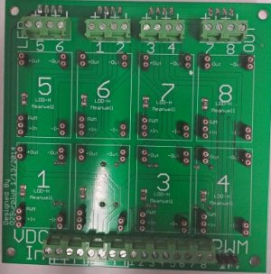
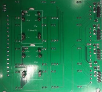
Meanwell LDD driver: for those who want to dim to 0 using Arduino

Good people, I have a Reef Angel and have the Rapid LED retrofits hooked to 4 Meanwells ELN-60-48P. What drivers do I need to control those lights 0 through 100%??
I wanted to see if I could find this on this thread... only it's 103 pages long!
Any info would be appreciated... If you know the answer and don't mind PM'ing me, I'd be forever thankful

I'ts relavent to the thread in my opinion anyway,

You need one LDD driver per ELN-60-48P (depending on your desired LED current you will choose the appropriate rated LDD driver, note it would be possible to technically run two or more LDD drivers off one ELN-60-48P if each string needed less than 650mA, at 650 you could have two LDDs, at 350 you could have 3 LDDs) So you may not need all your ELN-60-48P drivers running anymore.

You will also need a 5volt PWM signal from your Reef angle controller, you may be able to get this directly (I'm not familiar with the setup) or you would need a voltage divider to drop the 10v PWM signal down to 5 volts.
 
[QUOTEYou will also need a 5volt PWM signal from your Reef angle controller, you may be able to get this directly (I'm not familiar with the setup) or you would need a voltage divider to drop the 10v PWM signal down to 5 volts.][/QUOTE]

Sorry I don't know the Reef Angel but you should ask O2Surplus I think he has something which will do exactly what you want.
 
@ Pokahpolice

your power supplly, HLG-40H-48 is it the A or B model? From your sketch it would seem to be the B model, which does not have a voltage adjustment screw. It should still work but since you cant set the output voltage it may behave oddly? I don't know that I've seen this done before. Theoretically it should adjust itself to supply up to 48 volts if that is what the LDDs and LED strings are trying to pull from it.

Don't forget that the LDD needs 2-3 volts to operate so you basically need to count it as an LED. In your case you would actually only be able to run 12 LEDs per string.

Wattage rating of the PSU is not really important in this example, just know you will be using less than 40 watts, this is preferable as you never wan't to max out a power supply, though technically you can max out the HLG as it is designed to provide up to it's rated max voltage and current levels, unlike a standard voltage supply, which would be rated in maximum output only and not designed to run at that level for long.

I'm returning this power supply and buying something much larger and cheaper. Yesterday I FINALLY had a breakthrough and I understand how to calculate what I want. Back when I asked for suggestion I didn't even know how many LEDs I really wanted to power so I was way ahead of myself (no fault to anyone that gave advice). Thank you all for your help. It is very much appreciated. I'm sure as I move forward I'll get stuck and be asking again.
 
One more piece of advice,...if its not to late. Consider dividing your PS's up into a couple smaller units, instead of one large one. If a smaller unit goes out, your entire tank will not be without light until you can replace the faulty unit.
 
Pokahpolice,

I'm just curious why you pick 1w led vs higher power led? Ime, 1w don't have enough punch to penetrate regular tank and more work as well.
 
I got 3 of these in the mail today!!
:bounce1::celeb3::bdaysmile:

Thanks O2surplus!!!

These look awesome. time to fill them up :D
 

Attachments

  • 8UP LDD w-SCW-frnt.jpg
    8UP LDD w-SCW-frnt.jpg
    58.3 KB · Views: 4
  • 8UP LDD w-SCW-bck.jpg
    8UP LDD w-SCW-bck.jpg
    37.1 KB · Views: 8
I got 3 of these in the mail today!!
:bounce1::celeb3::bdaysmile:

Thanks O2surplus!!!

These look awesome. time to fill them up :D


You're welcome! :beer:
Go slow and line the components up carefully, before you attempt to plug in the LDD's and SCW's. I do my best to solder the mounting pins as firmly as possible, but they're less forgiving than the conventional chip holders we used to use, and may snap off if the components are misaligned.
 
the PWM header in picture 1 bottom right corner (pics from post above) is for fans right and the 2 scw on the bottom are for the power to the fans and then the 4 4 pin connectors on the bottom are to plug the fans in to be controlled by the pwm plug
Do I have this right
 
the PWM header in picture 1 bottom right corner (pics from post above) is for fans right and the 2 scw on the bottom are for the power to the fans and then the 4 4 pin connectors on the bottom are to plug the fans in to be controlled by the pwm plug
Do I have this right

Yes- you've got it right. I screwed up the silkscreen label for the 3pin fan control connections, so a brief description is needed.
Here's a photo with the pin assignments-

8upLDD-H_with_Dual_SCWs_zps6f239ef2.jpg


wiring diagram- (only shows three fan connections, but the board follows suite with one more connection added)

PWMfancontrol_zps8d422904.png
 
I'ts relavent to the thread in my opinion anyway,

Thanks man! I realize that I need to provide better info if I want more specific answers... So here it is I have 2 types of arrays:
1) All royal blues x 10 of the Cree XT-E LEDs (1500mA max. drive current). I have 2 of these, each connected to it's own Mean Well ELN-60-48P.

2) Cool Whites and Color LEDs x 14 of the XP-g and XP-E types (9 cool whites, 3 UV, 1 green and 1 red) The reds and UVs are 700mA max. drive current, the Greens are 1000mA max. drive current and the Whites are 1500mA max. drive current. Also 2 of these each hooked to its own Mean Well ELN-60-48P.

Each of these 2 types are hooked to one PWM 10V dimming controller on the ReefAngel.

The problem I want to resolve is that the lights don't kick-in until about 11% power and it's a big jump. I am trying to make it more subtle.

Also I was looking at the LDDs and found THESE.

Now, I have no idea how to go about it so any extra detail would prove useful for me so don't shy away :)

Thanks again!
 
1) All royal blues x 10 of the Cree XT-E LEDs (1500mA max. drive current). I have 2 of these, each connected to it's own Mean Well ELN-60-48P.
You will want one LDD-1000H or (HW) per string. Whether you use the pin version mounted to the boards discussed in this thread or use the wired version is up to you.

2) Cool Whites and Color LEDs x 14 of the XP-g and XP-E types (9 cool whites, 3 UV, 1 green and 1 red) The reds and UVs are 700mA max. drive current, the Greens are 1000mA max. drive current and the Whites are 1500mA max. drive current. Also 2 of these each hooked to its own Mean Well ELN-60-48P.
Now here you can potentially increase your level of color control if you want by having a separate LDD for each color. At the least what I might do is use an LDD-1000H (you'll need 2) for the Whites and use an LDD-700H (you'd need 3) for the colors. You could use a separate LDD for each color if you wish, combining the reds, greens, and UVs then splitting them up between the two PSUs so you have 10 whites, 2 greens, 2 reds powered on one PSU and on the other you have 8 whites, and 6 UV.


Each of these 2 types are hooked to one PWM 10V dimming controller on the ReefAngel.
How many PWM channels does your reef angel have?
you will use a voltage divider to drop that to 5v PWM for the LDD drivers (google it, easy to make, and been posted all over the forums) Your RA may have 5v pwm capability but it depends on the version you got, they are after all arduino based so have 5v pwm in there somewhere.
 
I like those little bridges for adjustment too. :D I don't know if Digi backed the 6211 order up another week or not,... but down to a few weeks now, and I think they are the last piece of my puzzle. Only good thing about the wait, was it feels less expensive gathering all the parts over a few months time.lol and I thought the boards were going to be my hold up,...lets see where in the heck did I put those darn things.:lolspin:
 
I stand corrected :wavehand: Did the 6211's show, or are you still working off your old stash?

Yep- All 300 chips arrived today, appear legit, and I'm soldering up a few for testing purposes. I've got a busy weekend planned, so I'll spend more time with these, next week. I'm going to solder up a batch of "Rott- Specials" first and then I'll get some into the mail for you - if needed.
 
Back
Top