Im not worried about the amp drop from the flicker. I am worried about driving the LEDs at 100% power. Whether doing it in PWM mode or not.
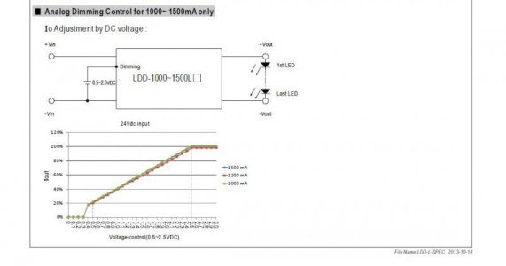
I didnt read the data sheet thoroughly btw. I thought I could lower the analog dimmer to lets say 2.3V, then apply PWM to that 2.3V signal. Unfortunately the LDD views 2.6V and higher as a PWM high, whereas 2.5V is full power for analog. So it definitely is one or the other.
No need for a voltage divider. The link I posted is a method to turn the arduinos 5V signal into a variable 0-5V signal. Ive already tested it. I can control the voltage down to the 0.01V consistently. It only requires a 4.7k resistor and a .1uf capacitor.
As for the pulsed analog output, only a test with a multimeter will tell if thats the case or not. crosses fingers

")

")