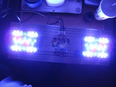
Meanwell LDD driver: for those who want to dim to 0 using Arduino

It was a new one. Here is the link to the one I purchased. I think it's just a no name Chinese ps.


Yeah "Buyer Beware" and all that. I've had the same experience. Some Vendors on Fleabay advertise MeanWell power supplies at "too cheap to believe" prices, and they are. They're cheaply constructed copies of MeanWell power supplies, i.e. Chinese counterfeits. All of the genuine MeanWell supplies that I own were made in Taiwan, not in mainland China.
 
Yeah "Buyer Beware" and all that. I've had the same experience. Some Vendors on Fleabay advertise MeanWell power supplies at "too cheap to believe" prices, and they are. They're cheaply constructed copies of MeanWell power supplies, i.e. Chinese counterfeits. All of the genuine MeanWell supplies that I own were made in Taiwan, not in mainland China.

Where do you buy your power supplies from? At this point I just want to get something reliable
 
Use a legitimate vendor like PowerGateLLC. They're selling the "real deal" for about $60.
SP-320-48 | Mean Well SP-320-48 | USA Warehouse

Yep. I got that one from Jameco for $66 plus $11 shipping, so a bit more expensive than PowerGate.

That Aimtec switching regulator that chicken posted looks just about right for me. Would get a 12v one and a 5v one and put a fan control pot after the 12v one.

Now a reason to learn Eagle and order some more boards at some point to get them off the breadboard they're sure to end up on. Wish I'd thought of this before ordering the O2Surplus 3-way ones cause I'd have mailed him some beer and asked him to add sockets for the two regulators on it somewhere. ;)
 
Thanks for the info guys. I looked at that one in the first place but I was trying to cut back on cost and it came back to bite me. Lesson learned!
 
O2Surplus,

Those green terminals that you are using will connect together to form a longer connector if needed. So you don't have to use them separated.

Danny
 
O2Surplus,

Those green terminals that you are using will connect together to form a longer connector if needed. So you don't have to use them separated.

Danny

Yes I know. I space them close enough together on the PCB to allow for the linking feature to work.
 
Just finished my build using 4 of these (2 @ 1000mA and 2 @ 700mA).

They work awesome! They're so small.

I've just got some more code to work out and I should have PWM up shortly with the arduino.
 

Attachments

  • IMG_1884.jpg
    IMG_1884.jpg
    59.2 KB · Views: 6
  • IMG_1878.jpg
    IMG_1878.jpg
    41.8 KB · Views: 5
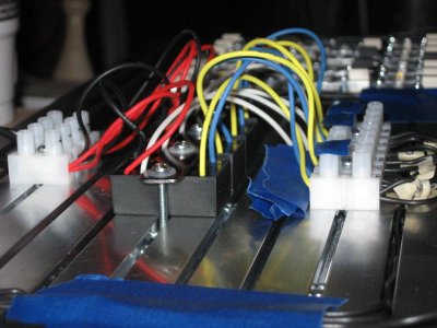
Okay so I'm having trouble dimming them... In the middle picture above the white wires are 0-5v PWM wires (according to the data sheet). So I tried to test one by connecting it to my arduino PWM i/o and the lights are one but nothing dims at all or turns off...

Does anyone have an idiot-proof wiring diagram to enable PWM dimming on these drivers?

Where is the PWM signal coming from? The controller sending the PWM signal needs to share a ground with the drivers. On the VIN side, not the LED outs.
 
everything shares a common ground with the DC power supply, just like in the diagram. If wired up the same as the diagram then everthing should be working. if not then your drivers and arduino have isolated grounds somehow and that needs to be corrected.

Hi Zachts: just read your answer and that made me think. I have a 12 V power supply for my arduino and a 48 V Meanwell power supply for the LDDs and LEDs. I connected the negative pins of the channel connectors in the Arduino (which positive is connected to the DIM pin in LDDs) to the negative of the Meanwell. Does that mean that arduino and LDDs do not share a common ground and therefore problems may arise?
 
Hi Zachts: just read your answer and that made me think. I have a 12 V power supply for my arduino and a 48 V Meanwell power supply for the LDDs and LEDs. I connected the negative pins of the channel connectors in the Arduino (which positive is connected to the DIM pin in LDDs) to the negative of the Meanwell. Does that mean that arduino and LDDs do not share a common ground and therefore problems may arise?

I don't understand how you have it connected.

What I normally do is connect the negative of the controller PSU (12V) to one of the negative terminals on the PSU for the LEDs (48V). Then I use a lead wire to go from the 48V PSU to the Arduino GND pin.
 
The controller sending the PWM signal needs to share a ground with the drivers. On the VIN side, not the LED outs.

Hi rrasco: may be my former question to Zachts has something to do with your answer.

The point is, if you use separate power supplies for the arduino and the drivers-LEDs, both power supplies should have their ground connected so there is a common ground for everything? Or is this an idiot question

That is correct. I was just replying to your question as well. :thumbsup:
 
I don't understand how you have it connected.

What I normally do is connect the negative of the controller PSU (12V) to one of the negative terminals on the PSU for the LEDs (48V). Then I use a lead wire to go from the 48V PSU to the Arduino GND pin.

AHHHHHH Great!!! I think that answers my question. I believe I now have the clue to my problems trying to dim the LDDs
 
I know this had already been covered but I am still a little hazy on this aspect.

Do I need to put a resistor on the pwm lines coming from the 5 up board if I am only running one driver per pin?

If so what size resistor?
 
I know this had already been covered but I am still a little hazy on this aspect.

Do I need to put a resistor on the pwm lines coming from the 5 up board if I am only running one driver per pin?

If so what size resistor?

You don't need to put a resistor on the PWM pin. Some people were doing it to prevent their lights from going 100% should the PWM signal be lost (controller turned off). If you do this, you ground PWM pin through a resistor. I don't know what size resistors people were using, it's somewhere in this thread.
 
I know this had already been covered but I am still a little hazy on this aspect.

Do I need to put a resistor on the pwm lines coming from the 5 up board if I am only running one driver per pin?

If so what size resistor?

Folks were using 10k Ohm resistors. On the O2Surplus 3-up boards he left room there for a 1206 size surface mount resistor. The 10k Ohm ones will say 103 on them. They're teeny tiny.

It sounded like if you don't have a spot on your 5 up board you can scratch a little open spot to the ground plane next to the PWM pin and ground that pin through the 10k resistor by soldering it to the side of the PWM pin and to the scratched out spot.

I have 100 of them which cost 1.88 cents each, and am only using around 10 to fill out my boards (when they finally arrive), so if you want to play with some, Kawi9_cf, send me a PM with a postal address, and I'll mail some to you in an envelope.
 
Im interested in using them but I dont really want to if its unnecessary. I will be powering the arduino with the same power supply so technically if the power is out the lights would already be out right?

At the same time I am all about fail safes.

I am still curious as to how this works.

So what your saying Eud is that on the bottom of the board I would solder one end of the resistor to pwm pin of the driver and the other end of the resistor to the scratched off area (common ground)? In normal operation the driver would dim through the arduino but if the power were to fail it would cause the current to ground out through the resistor keeping the lights from being at full power?

Im sorry if these are dumb questions I am very new to electronics.
 
Back
Top