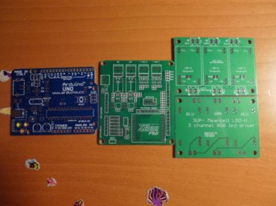
So what your saying Eud is that on the bottom of the board I would solder one end of the resistor to pwm pin of the driver and the other end of the resistor to the scratched off area (common ground)? In normal operation the driver would dim through the arduino but if the power were to fail it would cause the current to ground out through the resistor keeping the lights from being at full power?
Im sorry if these are dumb questions I am very new to electronics.
I'm only about 75% sure that that's right. I'm hazy on the subject myself, but that seems correct, yes. O2Surplus or some of the more experts here should confirm.

