Meanwell LDD driver: for those who want to dim to 0 using Arduino

"Eagle" is the name of the software. The free version will let you design two layer boards up to 100x80mm. There are some good tutorials on the website sparkfun.com on how to use it. I'd recommend downloading one of the already designed boards posted in this thread and modifying it to suit you, but starting from scratch isn't too hard once you go through the tutorials.
 
does anyone by chance remember the post page number, how to wire the drivers together to get "double amp" ( 2x .7 amp makes 1.4 amp when tied together )


I'll try and test, as what's the costs of a couple drivers..


thanks


btw. didn't get to say thank you to everyone who helped me with the amount of lines to voltage... in the middle of a move.. thank you!!
 
Joshlawless the last version I saw of your 6up board did not have the pull down resistors on it, is that correct, or did I miss it?

The regular board, not the one with the dip switches.
 
No, room for the pull-down resistors has been included on every version of the board I posted. If you follow the red trace from the "PWM" pin under each LDD, you'll see it connects first to one side of the pull-down resistor (looks like two small rectangles next to each other) before connecting to the screw terminal at the edge of the board.

The ones I ordered from iTead (v1.7) were just a little different from the one I most recently posted (v1.6)--I tinkered with aligning and centering things, and got a little creative with the decorations. I've attached a copy of the BRD & SCH files in one zip (these are what you can modify in Eagle) and a copy of the Gerber files in another zip (these are what you can use to order the boards from iTead or Seeed). The pictures illustrate the layout of each side (with the ground planes hidden for clarity).
 

Attachments

  • 6up-LDD_H_1.7-BRD&SCH.zip
    6up-LDD_H_1.7-BRD&SCH.zip
    74.7 KB · Views: 4
  • 6up-LDD_H_1.7-Gerber.zip
    6up-LDD_H_1.7-Gerber.zip
    72.2 KB · Views: 6
  • Board_1.7_front.png
    Board_1.7_front.png
    36.7 KB · Views: 4
  • Board_1.7_back.png
    Board_1.7_back.png
    24.8 KB · Views: 3
Thanks.
The parts are the same as what O2Surplus would have used on his 3UP RGB board?
Sorry if I'm asking too many questions, I have a tendency to overthink things sometimes.
 
The parts used to assemble the boards I posted are:
  • 3.5mm pitch screw terminals. I recommend using 11 of the 2-position kind that can slide together to build up larger (e.g., 4-position) blocks. I bought these. You can, of course, purchase 5 of the 2-position type and 3 of the 4-position type if you prefer.
  • 1206-style surface mount resistors (high resistance). I purchased these from Mouser.
  • 12x 2.54mm pitch header pins. These come in long strips that you can break into smaller blocks. Each jumper consists of a block of two of these pins soldered to the board. Here is a strip with 40 pins on eBay.
  • 6x 2.54mm jumper caps. You place these over the header pins when you want to connect the pull-down resistors. Here are some on eBay.
  • 24pin wide DIP sockets (6 per board). Here are some for sale on eBay. Note that these have the nicer machined pins.

The only parts you _need_ are the screw terminals.

The header pins, caps, and resistors can be left off, and you can still use the board to break out the connections from the LDDs to the screw terminals. If you don't solder resistors to the board, the jumpers and caps will be unnecessary.

The sockets just allow you to removably attach the LDDs to the board (i.e., you solder the sockets to the board, and just slide the LDDs in). If you'd prefer, you can just solder the LDDs directly to the board.
 
Thanks Josh.
Now I have to get up the courage to do it. I haven't do a project like this since high school electronics.
 
If you decide to go forward with it, read back a few pages to find a couple other people looking to buy some 6-up boards. Both iTead and Seeed make you buy in multiples of 10, and shipping from Taiwan/China can get expensive if you're in any kind of hurry. Splitting costs and slow shipping can get your per-board fab cost down to around $4 or $5.
 
2 Layer for the PCB is all that is needed, correct?

From What RRasco had on one of hie very early posts, the rest was...
1.6mm Thickness
HASL Surface Finish
100% E-test
 
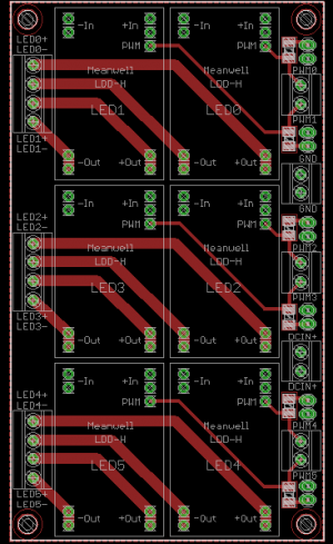
I have a strange problem that I'm having trouble tracing. I have a 48V DC power supply going to the inputs of my Meanwell LDD's and also to a 48V to 12V voltage converter. I use the 12V output to power three fans through a fanspeed adjuster as well as powering two Arduino boards that supply the PWM dimming signal.

I have tied together the DC negative of the Meanwell 48V output, the DC negative of the 12V output, and, by extension, the negatives of the LDD input and Arduino input and fan negatives are tied together.

When I turn on the main power, but keep the Meanwells off (I have the pull-down resistors installed and am supplying 0 duty cycle PWM at that point), I see my red LEDs flickering very dimly. If I turn the fan speed up the flicker goes away.

I've tried measuring continuity around the board and can see that the positive output of the LDD is tied to the positive input, but the negative is not. This is consistent with what others have seen where the current and voltage is adjusted by raising the negative.

Any idea where the red flickering could be coming from? Could it be a consequence of tying the input negatives together instead of the input positives? I know someone has posted on this thread before that it works better if the positives are tied together instead of the negatives.

Any suggestions?
 
Back
Top