Minimalistic multichip DIY LED build

@ Cmoua.

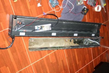
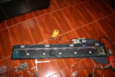
I have 9 pieces of 10-watt LED scattered on a heat sink with dimensions of 6 x 10 inches. 6 white and 3 blue. At 20 inches deep, I measure about 150-200 PAR below such a module. No lenses. With lenses, the PAR value is likely to improve significantly, especially if you choose 60 degrees lenses.

@ Sonny n Colleen

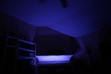
I think it would work well with 3 pieces of 50-watt hybrid chip, especially if you completes with a number 10/20 watt blue of different wavelengths. But it will be blue! :) Probably you do not need to use lenses, either.

Sincerely Lasse
 
Been following this thread for awhile now. I ordered (4) 10 watt and (1) 50 watt. My question is what are the dimensions for the two different chips? I would like the size in inches. Thanks
 
This thread is amazing. I think I have been out of engineering school too long. I never did well in the EE classes anyway, I guess i am more of a structural guy. I am setting up my dream tank. 54"x36"x25" tall (137x91x63). I Keep mainly SPS under 250w 20k DE metal halides. The LED multis have me thinking about changing my preferred lighting method. I can wire and fabricate but I am having a really hard time getting a parts list together. I really want dimmible LEDs so that I can smoothly simulate a dusk/dawn and I really like running actinic lights only while I am watching TV. I am not so worried about budget because I love to DIY over buying retail and it is like paying to have a little fun getting your hands dirty. Please help with a list. It would be most appreciated.

Edit- Multi drivers would be acceptable/expected. :)

-Derek
 
Great thread. Read through some parts but not the whole thing from beginning to end. I began a build using the 10 watt arrays back in January, before becoming aware of this thread. Based on some of the questions & info on the last few pages of this thread, I thought I might add my 2 cents & experience so far. My fixture is almost complete & has been running over my tank for just over a week. Some tweaking & a few more components to come, but here's a summary of what I have so far & I'm very happy with the result. Coral growth etc, will need to wait until more time has elapsed. Tank is a 4 foot, 77 gallon Hagen.

-Three rails of nine 10watt LED arrays each for a total of 27 LEDs,
-Two outer rails each have five 10000K White & four 452-455NM Royal Blue,
-Center rail has five 460-470NM Blue & four 6000-7000K White,
-Three 8 amp Dimmers, one controlling all the Whites & one each for the Blues & Royal Blues,
-One heatsink with fan per LED,
-One 250watt 12VDC power supply,
-Terminal boards, wiring, stainless steel hardware & aluminum angle stock,
-Mahogany veneer wood frame

Some photos:
I chose to solder the fan leads directly to the LED terminals, so they run at less than full speed. So far this has worked well, no issues with overheating. Fans need a kick start at low voltage settings, but once turning, will continue spinning at voltages as low as 3VDC.
P1040691e.JPG


Power supply with dimmers mounted in center compartment of stand. I used 14AWG single strand household wire from power supply to dimmers.
P1050405E.JPG


14AWG stranded wire from dimmers to fixture, 18AWG stranded between terminal boards then down to 22AWG single strand for each LED array.
P1050408E.JPG


P1050399E.JPG
 
Last edited:
With all of the talk about how efficient LED's are, why are they generating so much heat that needs to be dissipated by these massive heat sinks and cooling fans? Why does a 50W LED need a heat radiating system capable of dissipating 250watts of heat? If I switch to LED will I need to deal with 20+ fans running all day? My MH setup is perfectly silent except for a single low speed fan exhausting air from my canopy.

PS Nice setup mike.
 
Mike, Cool build. Are you saying you have a fan on every LED? I thought you could cool 10W LED's passively? Your heat sinks look like the ones on the ebay web site. Where did you buy the dimmers? What can you tell me about the MeanWell driver? I usually don't see a single driver for so many LEDs. Is the voltage adjustable? I see that the 250W will work. How are the LED's hooked up to it? I know on some threads there have been post regarding danger of shock? Sorry with all the questions. Your build looks great. Thanks---Rick
.
 
With all of the talk about how efficient LED's are, why are they generating so much heat that needs to be dissipated by these massive heat sinks and cooling fans? Why does a 50W LED need a heat radiating system capable of dissipating 250watts of heat? If I switch to LED will I need to deal with 20+ fans running all day? My MH setup is perfectly silent except for a single low speed fan exhausting air from my canopy.

PS Nice setup mike.

No - a 50 watt chip needs a cooling that can handle about 50 watts of heat that leaves the chip. It is true that it usually means an active cooling, usually a fan. I myself am fond of oversize cooling because the cooler I keep the chip, the longer life it has.

The advantage of LEDs is that they hardly any infrared radiation at all, ie the long-wave heat radiation. This means that you do not directly heat the water with the infrared radiation that is the case when using MH. The need for separate cooling of the aquarium is radically reduced when switching to LED.

@ Mike31154. Nice set up!

How have you wired your chip? What I can understand you have made a parallel connection of your chip and if you take the average you will have about 770 mA to each chip.

Sincerely Lasse
 
I thought you could cool 10W LED's passively?

You can cool any sized LED passively if you have enough surface area.

Those 10W LEDs will work just fine with the $5 heatsinks from AC-RC. I ran one in the bottom of my stand with the heatsink against the wood for over a week and it was barely warm.
 
I think have read 20W are ok with the AC-RC heatsinks also. I think when you get to the 50W is when you need the PCU coolers and fans.I suppose the enclosure needs to be considered also, fan or no fan.---RICK
 
I got my light fixture finished as well. So far, i am using 5x10w LEDS. I am very happy with the result. The light is actually brighter than it was in the picture. I am going to wait until my tank is up and running before making any adjustment (add more LEDs)
 

Attachments

  • led_materials.jpg
    led_materials.jpg
    30.6 KB · Views: 7
  • 10w_leds_fans_installed.jpg
    10w_leds_fans_installed.jpg
    31.7 KB · Views: 5
  • led_test.jpg
    led_test.jpg
    41.7 KB · Views: 10
  • led_on_empty_tank.jpg
    led_on_empty_tank.jpg
    85.4 KB · Views: 12
Mike, Cool build. Are you saying you have a fan on every LED? I thought you could cool 10W LED's passively? Your heat sinks look like the ones on the ebay web site. Where did you buy the dimmers? What can you tell me about the MeanWell driver? I usually don't see a single driver for so many LEDs. Is the voltage adjustable? I see that the 250W will work. How are the LED's hooked up to it? I know on some threads there have been post regarding danger of shock? Sorry with all the questions. Your build looks great. Thanks---Rick
.

Yes, every LED array is mounted to it's own heatsink/fan combo & yes you could also cool them passively if you use a large enough heatsink. In an effort to save weight & for longevity of the LED chips, I chose this configuration, maybe overkill but the fixture with all components weighs only around 12 lbs.

LEDs, heatsink/fans, power supply & dimmers are from eBay. Aluminum angle stock, wires, terminals & screws I sourced locally.

The 'driver' is actually a switching 12VDC power supply. There is no current control other than over current protection to keep the power supply from burning up. It has a small trim pot on it which allows voltage adjustment from about 10VDC to just over 13VDC. I've dialed it down to around the 10 volt mark & the dimmers provide additional voltage control to the LEDs, not current. I'm banking on the LEDs controlling their own current based on the voltage being fed to them. This is the advantage of a parallel set up. If one LED burns out or goes open circuit, that's all that happens, the remainder will keep working since they still see the same voltage from their respective dimmer. So current control is less of an issue than with a string of LEDs wired in series. Since I have the power supply set at 10 volts & the dimmers downstream of that, it's next to impossible to deliver too much forward voltage to the LEDs. The terminal boards on the top of the fixture distribute the wiring allowing me to run the leads for each LED to them. Some of the terminals have up to 4 sets of 22AWG wires from four LEDs connected to them. It's not that obvious from the photo since I only drilled a few holes for grommets to feed the LED wires thru the aluminum. Under the rails you can see a lot more wires from each LED.

Although you can see the sylized MW logo on the front of the power supply, I'm not sure it's actually a Meanwell product. The words under the logo are "MIEG WAEI". Maybe that's Chinese for Meanwell, I dunno. The price was right & it works as advertised. It has 3 sets of outputs to deliver the voltage, so I've used each pair to run wires to the Blues, Royal Blues & Whites. I plan to get two more power supplies to better distribute the load & allow each one to be on a separate timer. Additional dimmers are also in the mail so I can control the 10000K & 6000K whites separately.

As far as the shock hazard, well that's another advantage of LED lighting, it's low voltage compared to T5HO & MH set ups. The 120VAC in my build is relatively safe under the tank feeding the power supply. From the power supply up to the fixture it's less than 12 volts. I am thinking of putting a fuse on each line feeding up to the fixture though, more so to prevent overcurrent to the LEDs rather than as shock prevention.

Hope that covers all your questions.
 
@ Mike31154. Nice set up!

How have you wired your chip? What I can understand you have made a parallel connection of your chip and if you take the average you will have about 770 mA to each chip.

Sincerely Lasse

Thanks for the compliment Lasse. Yes, parallel connection. The 3 sets of leads from the dimmers feed the center terminal board. A jumper set for each color goes from the center terminal to the two outer terminals. This allows me to keep the 22AWG wires from the LEDs a little shorter. The terminals are large enough to take up to 4 of the 22AWG wires.

I haven't done any current measurement with the set up completed and on the dimmers, but it's something I should probably do. I took some current readings early on in the build when I was using 2 to 3 ohm resistors to knock down the power supply voltage. There was a slight variance between some of the LEDs at the same forward voltage, but the ones I tested were fairly close. Basically I'm not that concerned about the current since I have the power supply adjusted down to 10 volts & the dimmers downstream of that to further reduce the voltage as desired. As you know, maximum forward voltage varies somewhat between the different color LEDs, but they should all be able to handle 10 volts no problem & with the way I have it set up, it's unlikely that their maximum voltage will be exceeded.
 
Quick questions for Lassef and Mag..

How are you protecting the copper pipping over your tanks?

Also what setup would be good over a 34 Solana Cube?

Can you recommend LEDs for a 40 breeder?

Have you thought about Violets, Warm White and other colors that are turning up in builds?
 
Mike, Thanks for your reply to my question. After thinking more about your original post I had answer most of my own questions. Would you post a link to the ebay store you purchased your driver and dimmers. Also in typical 3W parallel builds I thought you used resistors and fuses directly after the drivers. The resistors to measure current to each string and the fuses are needed for protection in the event of loss of a LED in the string to prevent over current to the rest of the string.---Rick
 
Some photos:
I chose to solder the fan leads directly to the LED terminals, so they run at less than full speed. So far this has worked well, no issues with overheating. Fans need a kick start at low voltage settings, but once turning, will continue spinning at voltages as low as 3VDC.
P1040691e.JPG


Power supply with dimmers mounted in center compartment of stand. I used 14AWG single strand household wire from power supply to dimmers.
P1050405E.JPG


14AWG stranded wire from dimmers to fixture, 18AWG stranded between terminal boards then down to 22AWG single strand for each LED array.
P1050408E.JPG


P1050399E.JPG

Am I the only one that can't see Mike's pictures?
 
Back
Top