Minimalistic multichip DIY LED build

Thanks for the compliment Lasse. Yes, parallel connection. The 3 sets of leads from the dimmers feed the center terminal board. A jumper set for each color goes from the center terminal to the two outer terminals. This allows me to keep the 22AWG wires from the LEDs a little shorter. The terminals are large enough to take up to 4 of the 22AWG wires.

I haven't done any current measurement with the set up completed and on the dimmers, but it's something I should probably do. I took some current readings early on in the build when I was using 2 to 3 ohm resistors to knock down the power supply voltage. There was a slight variance between some of the LEDs at the same forward voltage, but the ones I tested were fairly close. Basically I'm not that concerned about the current since I have the power supply adjusted down to 10 volts & the dimmers downstream of that to further reduce the voltage as desired. As you know, maximum forward voltage varies somewhat between the different color LEDs, but they should all be able to handle 10 volts no problem & with the way I have it set up, it's unlikely that their maximum voltage will be exceeded.

Maybe I'm wrong, but in terms of power led, I am more concerned about over-current than for the overvoltage. It is the current that can burn them out. An example. You have a source that provides a constant voltage of 10 V and a current of 10 A. 10 LEDs that can handle 1 A. With a parallel connection, each chip would get its FV of 10 V and its maximum current of 1A. One fails and then the 10 A divided in 9 instead of 10 and each of the remaining chips will receive 1.1 A, and so on.

The multi-chip of 10 watt consists of 9 individual LEDs connected in 3 parallel loops with 3 LED in serie. This mean that if one LED is broken, it will not affect much, but if the whole chip break, the remaining will be affected with a current increases. Theoretically your setup will give a current about 770 mA (calculated from 250/12) to each chip and each chip manage 1 A. So the danger is not that great. It would require that it broke down 7 whole cip for you to have a current over 1 A. But as you pointed out, they have different FV and this can also affect how the current is distributed between the different chips.

So this is how I understand the problems associated with power LED. They are designed for a constant current, and not for a constant voltage

But your design is "up and running" so your design also seems to work.

Sincerely Lasse
 
Mike, Thanks for your reply to my question. After thinking more about your original post I had answer most of my own questions. Would you post a link to the ebay store you purchased your driver and dimmers. Also in typical 3W parallel builds I thought you used resistors and fuses directly after the drivers. The resistors to measure current to each string and the fuses are needed for protection in the event of loss of a LED in the string to prevent over current to the rest of the string.---Rick

I bagged the parts from several different eBay sellers to get the best prices. The better deals involved batch buys of 10 or more components. Took some shopping around & tried to use listings that offered free shipping. Prefer not to post links directly, but here are the sellers I've purchased parts from, you should be able to find their store that way.

6000K cool white LEDs - idmart
heatsink/fan - lucky_guy2010 & boyatech
12VDC power supply - lucky_guy
RB LEDs - luoxiquan
10000K LEDs - vitaric
Blue LEDs & 8amp dimmers - angel.edeal

I suppose I could start a build thread, but already have one going in a Canuck forum. If you're interested I can pm the info.

With respect to resistors in the circuit, in my case the dimmers take care of that. I opened one up to have a quick look & they consist of a potentiometer (variable resistor) & electronics on a pcb, presumably some sort of regulator. Resistors in the series builds are not to measure current, but to limit it in case of shorts or burn outs of LEDs in the string.
 
I can't see his pictures but I am work and they block all kinds of stuff.

All my photos are on the SkyDrive of my Windows Live account. They are in a public folder, so anyone who has the link should be able to see them. If not, it's either your service provider, a firewall or other software settings blocking the content.
 
Maybe I'm wrong, but in terms of power led, I am more concerned about over-current than for the overvoltage. It is the current that can burn them out. An example. You have a source that provides a constant voltage of 10 V and a current of 10 A. 10 LEDs that can handle 1 A. With a parallel connection, each chip would get its FV of 10 V and its maximum current of 1A. One fails and then the 10 A divided in 9 instead of 10 and each of the remaining chips will receive 1.1 A, and so on.

The multi-chip of 10 watt consists of 9 individual LEDs connected in 3 parallel loops with 3 LED in serie. This mean that if one LED is broken, it will not affect much, but if the whole chip break, the remaining will be affected with a current increases. Theoretically your setup will give a current about 770 mA (calculated from 250/12) to each chip and each chip manage 1 A. So the danger is not that great. It would require that it broke down 7 whole cip for you to have a current over 1 A. But as you pointed out, they have different FV and this can also affect how the current is distributed between the different chips.

So this is how I understand the problems associated with power LED. They are designed for a constant current, and not for a constant voltage

But your design is "up and running" so your design also seems to work.

Sincerely Lasse
Not sure your rationale of increasing current to the other LEDs in a parallel circuit if one shorts out works that way. In a circuit with parallel resistors yes, but I'm fairly certain LEDs don't behave the same way as resistors in a parallel circuit. My understanding is that provided each LED continues to see the same voltage, which is dictated by my power supply & dimmers, it shouldn't matter if 4 out of 5 LEDs in the parallel circuit short out, the 5th LED still sees 10 volts & will conduct only the current designed into it when manufactured (900mA @ 10 volts), no more. In a similar scenario with resistors in a parallel circuit, yes, if 4 out of 5 resistors short out, the 5th resistor now conducts way more current than when it still had it's buddies to share volts & amps with. When I did current measurements a while back, with 12VDC forward voltage & a 3ohm resistor in series with a white LED, there was only a minor variance in current between the four that I checked. Same idea with the Royal Blues.

When I first started looking at using these 10 watters I also noted as you explain that they consist of 3 rows of single LEDs in series/parallel configuration. Aside from the voltage required to drive them, I prefer them over the 20 or higher watt arrays since the individual LEDs on the chip have a little more room, i.e. they're not as tightly spaced as the higher wattage arrays. My theory there is, they should last longer since overheating is less likely. Still, I assume if one of the LEDs on the array shorts out, regardless of whether it's a 10, 20, 30 or 100 watt LED, it won't be long before there's a chain reaction (thermal runaway) & the whole thing burns up. One more reason I prefer the 10 watt LEDS, less costly to replace one than if a 100 watter cooks. Also why I have some confidence in my parallel set up & don't worry too much about current. Let the LEDs take care of their current based on the voltage they see.

If one of my dimmers fails open circuit, the LEDs will go out due to loss of power. No harm done, I simply get a new dimmer. If a dimmer fails short circuit, the LEDs hooked up to it will see the full power supply voltage which I have set at 10 volts, still within acceptable range of all the LEDs I'm using. Before finding the dimmers, I considered fine tuning the current to each LED by using a fixed value resistor & balancing them all out, but that's just way too much work & too many more components to be worthwhile. At the price of these 10watt LEDs, I'm fine with them slightly out of balance & if one burns out, no biggy, I'm only out a few $$s & they're simple to replace.
 
Mike,

Are you happy with the idmart chips? I was thinking about buying those.

They are the first few that I purchased back in October 2011 when I started thinking about a build with 10 watt LEDs. They're the 6000 - 7000K chips & if I remember correctly I got 2 sets of 2 at the time since I wanted to test the waters before going all out. Better deal might be the batch of 10 now with free shipping. They work fine as do all the others I've purchased from the different sellers. Pretty sure they all come from the same manufacturer. No duds from anyone yet.
 
Mike thanks for the info. Sure PM me your build thread. I'm interested in your housing and splash guard as to what you used. Thanks Rick.
 
Maglofster and Lassef, you guys are great and I'm sure everyone is thankful for all the advice you have given.

I have been going back and forth on this LED thing myself recently. I do have a deeper tank with the 90g (so 22" sand to top of water) but right now I don't have much in the way of coral. I would like to start adding more, but nothing too extreme (no clams and mostly soft coral). With that being said I've been looking at two options on doing these.

One is getting a 100w multichip on each side. Possibly also adding two 20w royal blues.

The other is to just get a 50w white with 2-4 20w royal blues.

This tank does have a divider in the middle, so I would really need to make two pendents of some kind.

My biggest concern is going to be with the colors. Right now I have a pretty white looking tank and would like to add a bit more blue to it.

Anyone have thoughts?

Thanks!
 
I understand your agony. Hybrid chips are blue and 16 000 and 20 000 K is not so blue mostly white. If you have a little patience and can wait a week or so maybe my current build of a 100 watt hybrid pedant is finished and I could take pictures with 1 pieces of 20 000 K and 1 pieces of hybrid chip next to each other. Maglofster currently have both versions running so maybe he has some advice too.

Personally, I might prefer the "clean" chip (either a color or the same K) and then mixing them. Then you can adjust exactly the color you want with the help of of dimming your chip to various degrees.

Otherwise I think the idea is good. 100 watts with lenses for penetration, and 20 watt for general effect. Maybe white pendents as head lights, and then a number of RB at lower effect to give the right feeling

Sincerely Lasse
 
Hi guys!! :)

Just wanted to check in on "my" thread and see what's brewing. :) I have been very busy at work lately and have had very little time for the hobby. A very big thanks to everyone who's contributing with pictures, comments and such! Thanks to LasseF for beeing a trooper and helping out with all the questions.
 
Ha, ha, yes. Good to see the OP back on the thread & liking what's been going on in his absence. IMO larger watt, multi chip array builds like the ones here will eventually take over & leave the 3 watt crowd in the dust.
 
I understand your agony. Hybrid chips are blue and 16 000 and 20 000 K is not so blue mostly white. If you have a little patience and can wait a week or so maybe my current build of a 100 watt hybrid pedant is finished and I could take pictures with 1 pieces of 20 000 K and 1 pieces of hybrid chip next to each other. Maglofster currently have both versions running so maybe he has some advice too.

Personally, I might prefer the "clean" chip (either a color or the same K) and then mixing them. Then you can adjust exactly the color you want with the help of of dimming your chip to various degrees.

Otherwise I think the idea is good. 100 watts with lenses for penetration, and 20 watt for general effect. Maybe white pendents as head lights, and then a number of RB at lower effect to give the right feeling

Sincerely Lasse

Thanks for your comment! I am in no rush (and no one in this hobby ever should be in a rush!). I am leaning more toward a 100w white with a 90 lense and then putting the 20w royal blue around it. Maybe start with 2 and move to 4 if needed.

Thanks for your advice, I'll check back for new stuff from you in a week!
 
Any Suggestions for a 96x30x30 reef tank I would to do a diy led fixture anyone have a price range for a tank this large.
 
I estimate that it costs between 300 - $ 350 to make a pendent that draws about 130 watts for my needs. For coverage of the entire aquarium, you should probably expect 5 such pendents.

It is absolutely not free even if you choose DIY solutions :sad2:. Maybe it is possible to squeeze costs in terms of cooling and drivers and you can also choose the sort of multi-chip that has its maximun at about 100 watts.

Sincerely Lasse
 
Quick questions for Lassef and Mag..

How are you protecting the copper pipping over your tanks?

Also what setup would be good over a 34 Solana Cube?

Can you recommend LEDs for a 40 breeder?

Have you thought about Violets, Warm White and other colors that are turning up in builds?

With splash guard of plexiglass.

I'm sorry but on this side of the Atlantic we do not know what a Solana cube is :)

If it is something similar to Red Sea Max 130, I've redone on my hood to have 10-watt LED. I'm not finished with construction yet, but it works.

Do not know what you mean by a "40 breeder"

Yes - a little. Warm White, I am not so interested because most corals live in the wild at depths where the red wavelengths do not penetrate down to. Violet, I will try in the next building.

Sincerely Lasse
 
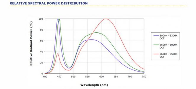
Lassef, you make an interesting point on the whites I haven't thought about. Are you saying the warm white has the spectrum more in the red range? Are you using the cool white?
 
Yes, Kelvin temperature is talking about how the relationship is between the short-wavelength (blue) wavelengths and the more long-wave (ie, in the first place the red). If you have a low color temperature (warm-white) it's likely that you have a preponderance of red wavelengths compared to the blue. Not always but usually.

Look at this spectral plot, taken from Cree's brochure on their XL-M chip. I think it illustrates quite well what I mean.

Sincerely Lasse

xm-l-spectra.jpg


I´m using 10 000 - 16 000 K as white, but I do not have cree.
 
Last edited:
Back
Top