Minimalistic multichip DIY LED build

This driver give you 2 options. You can adjust the current ("dim") with an internal pot (berween 1500 - 2000 mA) and you can adjust with a 1 - 10 V source. To do that manually - you need a power source that give you 10 V and you also need a pot. I´m not an expert of electronics, someone else here can probablt tell you which type of pot you need.

I see now at the data sheet that you need a signal to the dim wires just to have it to work. You have to get a 10 V source if you want it to work. Use the same as the one to the fan (hence drive the fan at 10 V) Datasheet

Sincerely Lasse
 
I see what you mean, so I guess I'll just buy a potentiometer and 10V power supply. From what I understand in your post though, I could just use a 10V power supply to run my fan (admittedly lower speed), and also power the potentiometer, therefor the fan would speed up and slow down based on the LED intensity also?

Thanks Lasse, good catch, I would have been wondering why there was no power to the LEDs when I got it all set up.

I thought you would put the fan before the potentiometer but hopefully it works the way you say also. Test - if it works - you hit two birds with the same stone.

Sincerely Lasse
 
So I haven't been on reef central in awhile. And have no desire to read 130+ pages on here lol.

I have a few questions.

1. Is the multi chip LEDs better than using a bunch of 3 watt cree LEDs?

2. Are they cheaper to build (LEDs, drivers, heat sinks.....)than building a big 3 watt led array?

3. Do they use the same or more electric that a 3 watt array? Do they last as long?

4. How hard are they to do compared to a 3 watt array?

Thanks
 
i have a few questions.

1. Is the multi chip leds better than using a bunch of 3 watt cree leds? Answer no and depends on who you ask

2. Are they cheaper to build (leds, drivers, heat sinks.....)than building a big 3 watt led array? Answer no

3. Do they use the same or more electric that a 3 watt array? Do they last as long? Answer depends and no

4. How hard are they to do compared to a 3 watt array?
answer depends
 
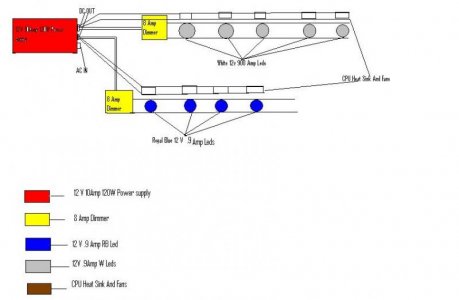
As Lasse mentions, using a constant voltage power supply can be tricky & risky. Having said that, my build uses similar components with respect to chips, power supply & dimmer. I have a total of 27 ten watt multichips and am running them in parallel using two power supplies on separate timers. Each of my chips is mounted on a heatsink with fan which makes for a lot of wiring, but it's a solution that provides subsantial weight savings over mounting them on a large heatsink. I've been running my fixture since April, so about 6 months with no issues other than a fan failure which was easily repaired, no damage to LED.

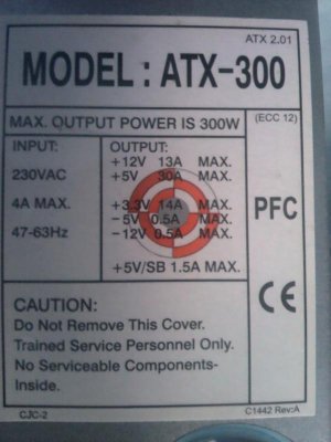
The two 12 volt power supplies are adjusted down to 10 volts output to keep them at or below the maximum forward voltage of the LEDs. The 8 amp dimmers further reduce the voltage and I run the chips at 8 volts or less to reduce the risk of burn out & subsequent increased current to remaining LEDs.

Based on my personal experience & if you keep the voltage out of the power supply at or below 10 volts, you might want to go ahead with what you have. You will need to hook up the LEDs in parallel and make sure you get appropriate heatsinks. A fuse in line with each LED would also help in the event one shorts or burns out. This will prevent the remaining LEDs from overcurrent.

If you wish to know more about my build, I have a DIY post on a canadian forum under the same user name. Below is a photo of the heatsinks I've used. A lot of soldering to hook up all 27 LEDs plus each fan, but the entire fixture weighs in at only about 12 lbs.

P1040642e2.JPG


P1050595e.JPG


P1050442e.JPG


P1050408E.JPG


A couple of the photos are older & I've made a few modifications since. One of the more important & time consuming changes was to rewire all the fans. Initially I had soldered the fan leads to the LED tabs, meaning each (12 volt) fan ran at the same voltage being fed to the LED. Problem with that was, that when the lights came on in the morning at low voltage (3 to 4 volts), most of the fans would not start. This is fine since the LEDs don't produce much heat at such a low voltage/current, but not ideal for when I'm not around to kick start the fan with my finger. So I finally bit the bullet & ran another set of wires from each power supply to directly feed the fans with 10 volts. No problems with start up at that voltage and the fans actually run quieter at the higher voltage. Some of them would produce an irritating whine at slower speeds. Now I can just set the voltage to 6 volts for the whites, 8 volts for the blues & go on vacation knowing the fans will start up reliably.

Might want to order a couple of extra LEDs & heatsink/fans for spare parts. An extra power supply would not be a bad idea either.


Thanksfor the help but sill I want to clear some doubts

Here is a diagram I made to show how I was thinking to connect everything


Everything would be in parallel

Please guide me if I am on the right track.

Thanks
 

Attachments

  • Power.jpg
    Power.jpg
    32.7 KB · Views: 10
I myself have used the 14,000 to 16,000 K white chip and RB chip at 445 and 455 nm. 1:1 and dimmable drivers.

No I recommend that you use constant current drivers. As I wrote in another thread -

Sincerely Lasse

Hi agian Lasse

What are the disadvantages or risks if I use a PSU instead of drivers?

attached you can find a pic of the power supply in question
Thanks Daniel
 

Attachments

  • 2012-09-27 16.47.29.jpg
    2012-09-27 16.47.29.jpg
    46.5 KB · Views: 5
Talk to me a little about light and depth. I am looking at two scenarios here.

One is the 3 watt single emitter (is 3 watts really a single emitter?). Placed x amount above the tank, it has enough punch to reach the bottom, for, lets say a 1"diameter on a 24" tank (this is for example only). Place enough 3 watts side by side, and, you can cover the whole bottom of the tank with the same, even, light/PAR. This would be spread evenly through out he bottom from left to right, front to back evenly.

Second, we have the single chip, but, there are two theories I am dealing with. One is the single large 100w type chips. They should have good, fairly even spread, but, they are not like regular bulbs where light is radiated in equal amounts in all directions. Even though they say they radiate 180 degrees, I do believe a lot of the light is non directional light, as opposed to light perpendicular to the LED. I could be totally wrong on this (thats why I am discussing it) or just over simplifying the whole thing. So, if a 100w chip is in the center of, say, a 25"width span, will the light be even at the bottom like 3 watt LEDs spaced evenly to the ends? The answer could have somewhat ramifications to coral placement.

Second to the second, is, if you have multi 20w leds of different colors, aka blending as opposed to 2 100w chips. I was thinking 1 20k 100w chip next to a 100w 450nm. This would be for ease of assembly, then I thought, how well would it blend? 3w b/w/b/w/ blend pretty good from what i have seen. I dont think I have seen a 100w next to another 100w of a total different color to see what it blends like. If I go 20w chips, (now that I have redesigned it in my head for the 40th time) I would place the 445mn in a "X" shape. That would give me 100w of 445nm but I would only have 80w of 20k around it if I were to try to condense it together. My question is, would that blend good or will I have w/b separation at the bottom of the tank and or on objects?

A final twist to all this while I was typing is, you have x amount of PAR at center bottom of 24" tank (for example) for a 3w LED. Am I to assume that a 100w chip with have higher PAR at the center point of the chip at the bottom of the tank? Its an odd question to me because if the chip is a 2.5 watt chip, even thought they are all next to each other, thats still 2.5 watts shining straight down, but, of course if you add it all up.... This is where physics start to elude me.


Sorry all, am not trying to be a party pooper on LED chips, but, if they are not the best way to go, I just want to know why and go the best route.
 
Last edited:
Hi agian Lasse

What are the disadvantages or risks if I use a PSU instead of drivers?

attached you can find a pic of the power supply in question
Thanks Daniel

An LED is a diode and a diode has not a linear relationship between voltage and current as the resistance is large in the beginning and at a given voltage (FV) it will be very low.

As an example: Cree's XM-L LED.

At a voltage of 2.8 V, the current is 400 mA. At 3 V, the current is 1100 mA and at 3.2 V, the current is 2100 mA. At a difference of 0.4 V, the current increases by almost 1700 mA or more than 5 times.

As it is amperage that burns down our chips, it's much wiser (and safer) to use a source that provides a constant current and varying voltages after the load.

I'm not saying it is not possible with a constant voltage source, but it requires a lot more knowledge and fine-tuning especially if you are close to the chips FV.


Sincerely Lasse
 
@ reefurchin: Look at this, not for the colours but for the blending. 1 20 watt red chip i the middle; two white and two blue in a X (10 watts). The last picture is white in real life and for my eyes.

The other questions you take up has been answered many times in this thread or at least - there is a lot of different opions. I´m sorry - i do not own the holy grail - you have to decide by your self what to do :)

Sincerely Lasse
 
Oh, I see, getting back at Americans by making me sweat it out trying to read Sweden, ehy, lol? Good link, lots of pics, thanks.

Well, if you dont have the holy grail, who does? I would not mind trying things out to see what I like if I could send all the un-needed parts back, but, I think if I tried all combinations and had to keep all parts, it would end up costing me $5,000 or so. Okay, more like $1500+ if I was not to exaggerate. Sadly, my budget is $400, which I could do, IF I knew the winning combination, which I dont, as of now. :(
 
We have a saying here in Sweden: It is possible to skin a cat in many ways.

I chose 10 W multi chip when I built my first LED design just because it was not possible to obtain white 3 watt LED at 10,000 to 16,000 K. I did not want to make use of the large chips (30 - 100 W) because I wanted the opportunity to vary my light over the aquarium.

However, you are wrong when you say that the large chips do not provide an evenly distributed light. They provide a good distribution of light and with the help of lenses you can get a good penetration. The Dream Chip developed (with 5 separate channels) provides the best of both worlds - variation, penetration and uniform distribution of light.

It is clear that you can achieve this with the help of 3 watt LED as well but I do prefer to work with multiple chips.

There are two different mindsets, so you must decide what path you should follow. I do not think it will be cheaper to multi chip; you should invest in quality there too.

Sincerely Lasse</SPAN>
 
Hi Lasse, thanks for the extra info. I think I may be over thinking this, but, it is only for the health of my tanks corals. I only have enough money to get it correct the first time so I have to check, double check and triple check, so, I hope you understand me beating a dead horse.

See, the way you have yours is great. Like you said, colors to blend, but, you notice there is nothing on the edges, its all centered. I assume thats enough for the tank to get proper coverage to the edges? I have to go back and read your thread (in Swedish) from front to back so I can at least look at the pretty pictures, lol. Are there any other threads you know of that show tanks with different setups? Also, when are the multi dream chip users going to show theirs off? Could you post us some links here too whenever you get a chance? Tomorrow, provided my work computer actually works, I will search google on led dream chip and see what that brings up. Cant wait to see pics of that!!
 
An LED is a diode and a diode has not a linear relationship between voltage and current as the resistance is large in the beginning and at a given voltage (FV) it will be very low.

As an example: Cree's XM-L LED.

At a voltage of 2.8 V, the current is 400 mA. At 3 V, the current is 1100 mA and at 3.2 V, the current is 2100 mA. At a difference of 0.4 V, the current increases by almost 1700 mA or more than 5 times.

As it is amperage that burns down our chips, it's much wiser (and safer) to use a source that provides a constant current and varying voltages after the load.

I'm not saying it is not possible with a constant voltage source, but it requires a lot more knowledge and fine-tuning especially if you are close to the chips FV.


Sincerely Lasse

ok..so last time you told me to use the ELN-60-48 (p or d) and it is possible to connect 4 pieces 10 watt LED in series to each driver. can you please post me from where i can buy them from ebay!? At first im going to run a test run with 3 leds. is there another driver available rather than the ELN 60-48. can you please PM if itd not possible to post advertising here? thanks
 
Hey Lasse!

I have a question regarding multi-chips.

I have a 6' 180gallon and have three arrays over the tank. Each array has 2 X 20W white, 4X 10W actinic (white 10X + blue 450nm), and 2X 10W 460nm chips. The 20W are 1:1 with a driver, and the 10W are 2:1 to a driver ran in series.

I am using the Sure electronics PWM 10/20w drivers and running them all off a 24V 14.6a power supply.

Specs are as follows:

White:
DC Forward Voltage (VF): 15 ~ 17 Vdc
DC Forward Current (IF): 1200mA ~ 1300mA

Actinic:
10W Actinic:
DC Forward Voltage (VF): 9.0V-11.0V DC
DC Forward Current (IF): 900-1000mA

Blue:
Forward Voltage :10- 11V
Forward Current : 1000mA

Now, the Sure drivers are 1500MaH. Will this be an issue later down the road? Am I putting too much current through the 10W LEDs causing them to overheat? If so, how can I lower the current while still using the same power supply and drivers? If I have to, I will order lower-current drivers from Sure. I currently have 15 total drivers wired to the Power supply.

driverFarm_zps2e1b5aec.jpg

Array3_zpscbf20b5e.jpg
 
Back
Top