You are using an out of date browser. It may not display this or other websites correctly.
You should upgrade or use an alternative browser.
You should upgrade or use an alternative browser.
Must-haves for EASY DIY controller?
- Thread starter der_wille_zur_macht
- Start date
der_wille_zur_macht
Team RC
Optiboot is fine.
ZenMastr1968
New member
der_wille_zur_macht
Team RC
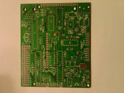
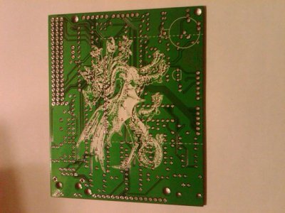
Hooray! Multiheaded silkscreen madness!

der_wille_zur_macht
Team RC
I should make a few comments. The images that Zen posted are NOT the most recent rev of the board, but that rev and the final rev are electrically identical.
The differences are as follows:
1) The silkscreen for U11 is printed on the wrong side of the board in that version. The current files on google code have this fixed.
2) The two dotted lines on the bottom indicating the "safe zone" for a standard Arduino shield have been removed in the latest rev, since they don't really apply and they get in the way of the dragon.
Zen, one thing I am very interested in is to know if the board house printed silk on the pads, or did they trim it? If they printed silk on the pads, soldering is going to be a mess.
ZenMastr1968
New member
i'll look closer when i get home tonight and see if I can't get a magnified pic.... that was just with my blackberry.
I didn't start soldering yet - was going to compare my inventory against the latest BOM to make sure I had the right parts....
I didn't start soldering yet - was going to compare my inventory against the latest BOM to make sure I had the right parts....
Last edited:
DustinB
New member
No need for a magnified pic. There was just some concern on the possibility of the silk layer not being masked in relation to the solder pads. We were unsure if some of the silk may have been printed on the solder pads causing an issue with soldering, cleaning the silk off the pads being a PIA solution.
As long as the logo is not printed directly on the solder pads we are in good shape. Looks to me in the pic that no silk is on the pads. Are all the solder pads clean?
As long as the logo is not printed directly on the solder pads we are in good shape. Looks to me in the pic that no silk is on the pads. Are all the solder pads clean?
der_wille_zur_macht
Team RC
i'll look closer when i get home tonight and see if I can't get a magnified pic.... that was just with my blackberry.
I didn't start soldering yet - was going to compare my inventory against the latest BOM to make sure I had the right parts....
Unless you actually used the current BOM to shop with, you probably don't have the EXACT right parts. We switched a few of the small SMT components (a cap and inductor near the Ethernet chip) to through hole. I think we also eliminated one of the electrolytic caps near the slave AVR.
ZenMastr1968
New member
For the most part, I think they did a decent job keeping the silk screen off the pads. There are a few spots where it's close....


I'm not worried about my parts in relation to the BOM - I know some of the parts changed. I bought all my stuff back in April/May so for the most part I should be ok - just want to be precise, thorough, and be on the apples to apples page for testing purposes....
I'm not worried about my parts in relation to the BOM - I know some of the parts changed. I bought all my stuff back in April/May so for the most part I should be ok - just want to be precise, thorough, and be on the apples to apples page for testing purposes....
Hey guys sorry to interrupt. The board looks cool. I just wanna know if there's an alternative to part HR911105A cause its not available anywhere other than on ebay and i cant buy on ebay cause i dont have a paypal account and i cant make one cause my country is not in paypals list.
der_wille_zur_macht
Team RC
sparkfun, seeedstudio, and iteadstudio have all either carried them in the past or indicated that they would carry them in the future. I would email each of them and ask if they will have any soon. If you get totally stuck send me a PM and I'm sure we can get you one somehow.
der_wille_zur_macht
Team RC
Looking at the photo you took of the other side it looks like there was one other addition to the silk that didn't make it in that rev...
DustinB
New member
sparkfun, seeedstudio, and iteadstudio have all either carried them in the past or indicated that they would carry them in the future. I would email each of them and ask if they will have any soon. If you get totally stuck send me a PM and I'm sure we can get you one somehow.
Unfortunately when the sparkfun rep told me the magjack they carried was similar to the HR911105A, they were incorrect. I believe the sparkfun jack is similar to the HR911102A. Same pinout as the ...05A, but the internal wiring is a bit different and does not work with the hydra.
The only place I have seen these jacks being sold online is on ebay unfortunately. No word back from itead yet about the jacks being carried, but they only accept paypal anyway I believe.
ZenMastr: As long as there is no silk on the silver pads we are good to go. Thanks for the pics! As for differences in parts, if you had the entire BOM already you will only need 2 parts. L1(ferrite bead) was replaced with a through-hole part, and the only surface mount capacitor was replaced with a through-hole(I don't know the number offhand). Other than that, you will end up with an extra cap or 2 left over.
der_wille_zur_macht
Team RC
It's also VERY VERY VERY important that you check part numbers against the schematic when mismatching BOM and PCBs! We renumbered the board a few times after removing the errant electrolytic cap so some of the numbers may be off by one. In other words, the part that was in the old BOM as C11 may be C10 now.
ZenMastr1968
New member
I started going through the latest BOM and comparing parts to actual part numbers, but thanks for the heads up about the component numbering. I'll watch for that too....
der_wille_zur_macht
Team RC
I'd just hate to see you put a 10uF electrolytic where a .1uF ceramic was supposed to go just because we renumbered! ")
terahz
1x10^12 Hz
Since a bunch of you might have the board ready soon, just wanted to point out that there is one hardware configuration step for the PH - calibration.
It is quite straight forward and there are 2 ways to do it - with LCD or with multimeter.
Prerequisites:
7.00 PH Calibration fluid
10.00 PH Calibration fluid
4.00 PH Calibration fluid (optional)
LCD:
For this method you need to have your LCD connected and a firmware uploaded to the main AVR that will display the PH value.
- Connect your PH Probe to the BNC connector
- Power up Hydra with PSU (5V from usb cable will not work, the PH circuit requires more than 5V to work)
- Dip your probe in RO/DI water to wash it.
- Now dip it in the 10.00 PH fluid. Leave for a few minutes. When you come back, adjust RV3 until the display reads the corresponding PH for the corresponding temperature (should be on your fluid packaging, usually 10.00 is @ ~77F). Leave for a few minutes. If the number has drifted, adjust.

- Repeat the above 2 steps with the 7.00PH Fluid and RV2.

- Repeat above 3 steps to make final adjustments.
(Optional) Dip the probe in the 4.00 PH fluid and wait a few seconds. The display should be pretty spot on (mine reads 4.01 which is good enough for me).
Multimeter:
The steps are basically the same, but instead of using the LCD to read the value, use a multimeter and read A3 on the main AVR. For 10.00 PH you should have 2.441V, for 7.00 you should have 1.709V. Now depending on the quality of your multimeter, the arduino LCD might be more accurate.
Ideally it shouldn't matter how you calibrate. But that's ideally
EDIT: now I have to see why the above don't match in my case
It is quite straight forward and there are 2 ways to do it - with LCD or with multimeter.
Prerequisites:
7.00 PH Calibration fluid
10.00 PH Calibration fluid
4.00 PH Calibration fluid (optional)
LCD:
For this method you need to have your LCD connected and a firmware uploaded to the main AVR that will display the PH value.
- Connect your PH Probe to the BNC connector
- Power up Hydra with PSU (5V from usb cable will not work, the PH circuit requires more than 5V to work)
- Dip your probe in RO/DI water to wash it.
- Now dip it in the 10.00 PH fluid. Leave for a few minutes. When you come back, adjust RV3 until the display reads the corresponding PH for the corresponding temperature (should be on your fluid packaging, usually 10.00 is @ ~77F). Leave for a few minutes. If the number has drifted, adjust.
- Repeat the above 2 steps with the 7.00PH Fluid and RV2.
- Repeat above 3 steps to make final adjustments.
(Optional) Dip the probe in the 4.00 PH fluid and wait a few seconds. The display should be pretty spot on (mine reads 4.01 which is good enough for me).
Multimeter:
The steps are basically the same, but instead of using the LCD to read the value, use a multimeter and read A3 on the main AVR. For 10.00 PH you should have 2.441V, for 7.00 you should have 1.709V. Now depending on the quality of your multimeter, the arduino LCD might be more accurate.
Ideally it shouldn't matter how you calibrate. But that's ideally
EDIT: now I have to see why the above don't match in my case
Last edited:
terahz
1x10^12 Hz
OK, so looks like the PH calibration is going to be interesting. I got the voltages based on the text that came with the PH circuit, but after I ran the numbers myself, I get different voltages... That being said, just skip the multimeter calibration above and do it with the LCD, that will be good enough. Right now we have a factor of '50' that converts the AVR reading to PH, but we might change it to '46' as that seems a bit closer to my calculations. Either way, the outcome should be the same. Changing the factor it will just shift the resolution which is probably higher than that of the probe anyway so it doesn't matter. Enjoy.
Similar threads
- Replies
- 6
- Views
- 2K
- Replies
- 0
- Views
- 1K
- Replies
- 2
- Views
- 271