Must-haves for EASY DIY controller?

OK.......

I thoroughly examined my board - didn't see anything wrong. Cleaned the backside again - gently - with alcohol and a toothbrush to make sure there wasn't any flux messing things up. Still nothing happening on the ethernet front. Started checking currents and voltages at certain pins and comparing the results to the schematics and the data sheet for the 28J60 and still nothing blatantly wrong so today I decided to just try replacing the 28J60 (since I had a spare) and Volia....

link and ethernet web server demo sketch load and function properly!

I don't have any probes or sensors yet, so I can't check that side things yet, but now off and running....
 
What does it take to load a sketch besides something like a BUB? I see people mention compiling the sketch and uploading. What kink of compiler is required?
 
FTDI is needed to upload. Do a search for FTDI and youll find pre-made and DIY options. THe firmware is uploaded to the chips via the arduino software which can be had for free at www.arduino.cc
 
I assume doing it over a com port would be fine too, given that you have a ttl to rs-232 converter? slower, obviously, but would work ok.
 
Yes, you can do it via a serial port if you have a TTL to RS-232 converter. Most people would find it more convenient to just use TTL-USB, i.e. the BUB from modern device or any of the FTDI cables or breakouts.

And as mentioned above, the only thing you need in your toolkit from the software side is the Arduino IDE. It lets you author code, and simply push a button to compile and upload. You don't need to understand the guts to get it to work.

do we need the 3.3V or 5V FTDI cable?
 
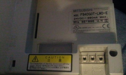
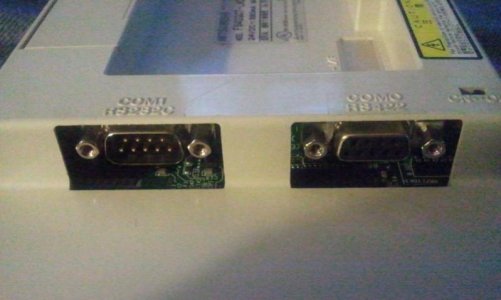
I was wondering if this would work in place of the lcd and keypad. It is a touch screen graphic operation terminal used in factorys to control robots and other machines. It is a mitsubishi f940g0t-lwd-e
 

Attachments

  • 2011-01-26 13.47.59.jpg
    2011-01-26 13.47.59.jpg
    36 KB · Views: 8
  • 2011-01-26 13.48.18.jpg
    2011-01-26 13.48.18.jpg
    38.7 KB · Views: 8
Last edited:
I'm not familiar with that particular unit but at first pass it strikes me as being in a different league than the stuff we're talking about here. More powerful and more complicated to control. Even low-end touchscreen color displays are cumbersome, and this one's not low end.

If you want that sort of interface, look at seeedstudio and iteadstudio's stores - they both sell touchscreen displays that would be more appropriate.
 
i was just wondering because i got this one for free at work because they were going to throw it in the trash because they put in newer ones
 
I'd hang on to it. The trick might be finding a specification of how to feed it information. You may be able to build an Arduino-based controller that JUST runs the display, and passes I/O back and forth with a Hydra.
 
I'm trying to get my head wrapped around the use of the address jumpers on the relay board. If I understand it, this allows the use of more than one relay board by daisy chaining them together and setting each one to a unique address. Could anybody get me an example of a code snippet to target a specific relay.

Also, what about a gerber zip file for the relay board and BOM.

Thanks for all you guys have done and are doing. I hope I don't come across as being a PITA! :worried:
 
I'm trying to get my head wrapped around the use of the address jumpers on the relay board. If I understand it, this allows the use of more than one relay board by daisy chaining them together and setting each one to a unique address.

Yep, that's it. I2C is a bus. Each device on the bus has a unique address. Any time a master on the bus wants to communicate with any other device on the bus, it does so by specifying the address of the target device.

Some higher-functioning chips (i.e. the AVRs we're using) let you set their address at runtime in software. This is super-flexible because you can change a bit of code and get a different address - you don't have to go back to the drawing board. Other devices (i.e. the MCPs and almost all other devices meant to be used exclusively as slaves) aren't that smart, and you typically set the address at "implementation time" by hardwiring a given set of address pins high or low. This is cheap but totally inflexible. Once you've built such a device, you cannot change it's address, which means there's no way to resolve conflicts or use several such devices on the same bus.

Using jumpers on a "hardware-addressed" device gives you a mix of the two possibilities. You can change the address without going back to the drawing board and remanufacturing the circuit. This lets you resolve conflict by changing the position of the jumpers on one of the boards, and then updating your code so it knows the new address.
 
I'm trying to get my head wrapped around the use of the address jumpers on the relay board. If I understand it, this allows the use of more than one relay board by daisy chaining them together and setting each one to a unique address. Could anybody get me an example of a code snippet to target a specific relay.

Also, what about a gerber zip file for the relay board and BOM.

Thanks for all you guys have done and are doing. I hope I don't come across as being a PITA! :worried:

I've got a zip of the gerbers... Itead just shipped out my boards...
Who can I send it to for placement on the google code site?
 
So in the next few weeks I will be getting my new tank which will be a 300 gallon wide. I am currently running LEDs over my 75 gallon (which will be upgraded to go over my 300) and would like to control them through PWM and add a pH monitor along with the relays for controlling pumps and temp sensors. I was wondering if someone would be able to point me into the right direction as for pricing of materials. I have found everything needed for the controller itself which comes to 116.10 (not including shipping). Can someone point me in the right direction as far as cost/links for what is needed for the relays, pH probe and temp sensors?
 
Temp sensors, will be up to the end user. Browse through this thread will shine some light on what a few have played with. The pH probe can be had from Bulk Reef Supply. DustinB and I (read mainly DustinB)worked on a relay setup that uses the Chauvet SR-8 Relay and a custom board. The chauvet can be had from an online music equipment retailer. Terhaz used a opto isolated 4 relay board from Futurlec.

More specific questions will yeild more specific answers. But I hope that helps some.

Any particular brand/model of PH sensor?
I've found them from 40 bucks to almost 300!
 
Back
Top