Must-haves for EASY DIY controller?

is it possible for you to add a "parts" page to the wiki? (or is there one that I haven't found yet?) I found the "Assembling" page, and it does a great job describing the parts, but not where to obtain / purchase them. Also, it is not fully inclusive - like all the little parts I might need to put it together... ?? Is this what the Hydra BOM does? If so, how do I read it after I unzip the file?I'm trying to come up to speed on this project and find it hard to put my finger on what the current recommendations are. Also, a list of places (URIs) that you have purchased these parts from would be nice. (no research here, just documenting the path that you guys have taken.)

ps - curious - why the q/a here on RC and the main info repository on wiki? why not discussion / blog on wiki too? 65 pages and growing seems like it makes RC a difficult location for FAQ or answers to questions that others might benefit from... just a thought....
 
jedidog1, it will probably work.

saltySamuri, since you've seen the assembling page, it has a direct link to the spreadsheet listing all part numbers from 2 vendors - Mouser and DigiKey. All you have to do is use one of their BOM import tools and copy/paste the column.

Since this project started here on RC, we want to keep it that way and just use the wiki as the latest summary. If you'd like to contribute to the wiki, please do so. FAQ section sounds like a good idea.
 
Sorry, I don't have time to wade through 63 pages of geek-gasmic fun atm, but, is there a schematic for the PCB board hidden somewhere in the dark cobwebbed corners of the Wiki, or this thread?
 
I see two facets to that question:

1) Do their components meet the spec required by this design? Should be easy to answer by comparing the specs on their website to the specs for the parts in our reference materials.

2) Do you trust that what you're buying from them actually meets the specs they list, or might they be subbing in low-quality stuff to hit a low price point? I dunno how to answer this other than trust or past experience with the vendor in question, and I've never used that shop so I dunno.
 
I have one small problem. Output on 7660 is 0.55, not negative Vin. Because I have not build relay board from where I will get 7.5V input voltage I am using temporary power supply with 10.1V, input on 7660 in 9.76V.

I have checked ground on pin3 and U11 both is correct. Do you think 9.76V is too much, could I damaged 7660? Can I use 7660A rated 1.5-12V instead?
 
Do you have correct voltages everywhere else on the board? Is the whole board populated? Can you post a photo so we can verify you have things correct?

Start by double-checking part orientation for the WHOLE board.

Can you provide a link to the EXACT 7660 part you're using now? There are a bunch of manufacturers/versions with different tolerances and voltage capabilities.
 
Yes, everything else is OK. I have measured exactly 5.0V on board and Ethernet is working so I suppose 3.3V is also correct. I was checking PWM for leds and it seemed be OK (level 10 of 255 ~ 0.5V). I am using ICL7660CPA-ND from DigiKey. Please see the board, LCD and web interface.

Once again thank you and all other for this great project.
 

Attachments

  • HydraPCB_Top.jpg
    HydraPCB_Top.jpg
    77.1 KB · Views: 13
  • HydraPCB_bottom.jpg
    HydraPCB_bottom.jpg
    74.3 KB · Views: 20
  • Hydra_LCD.jpg
    Hydra_LCD.jpg
    35.2 KB · Views: 12
  • Hydra1.jpg
    Hydra1.jpg
    20.3 KB · Views: 12
Are your caps oriented correctly? The C29 and C36 need to be "backwards" in that their positive pins are on GND. I can't tell from your photos.

Hard to say what's wrong - the part you used should be OK at 9.76. Might try swapping another and see. Or pull it out and take a reading on each of it's pads on the board to see if there's an outside influence.
 
I have checked polarity of electrolitic capacitor C29 anc C36 and both have - electrode opposite to + sign on PCB. I am using 10uF/35V/85°C. See the attached makro photo of 7660 part of PCB.

I have also measured voltages on all pins with and without 7660. Strange is that there is 0.65V on -Vout and 0.83 on U11/Pin3 (U8/Pin11, U9/Pin4)

Thank you very much for your help
 

Attachments

  • Hydra_7660.jpg
    Hydra_7660.jpg
    77.8 KB · Views: 12
  • Hydra_7660_U.jpg
    Hydra_7660_U.jpg
    16.3 KB · Views: 11
Did you test the board for shorts or broken traces before building? This is really hard to do once there are components put on it.

If I were in your shoes, I would probably put in a new 7660 and see what happened. If nothing changed, I'd swap the other components in it's immediate circuit (the caps and so on). I would probably also cut the trace leading from it to the pH circuit to eliminate interference from that portion of the board (assuming you fix the problem, you can bridge the cut trace with a blob of solder).
 
No I did not measure PCB for shorts and broken traces before soldering.

I have removed 7660, U8 and U9 and measured all electrolitic caps: both C28 and C29 have 9,74 uF, but by C36 my multimeter UNI-T UT71C cycles between measuring and 12.7 uF. I have also measured -Vout on 7660 with U8 and U9 removed and there is 0.37V. So I will replace C36 and if this not helps than 7660A.

dwzm thank you for your advices
 
2 Relay boards (4 relays each) on second MCP23008 controlled with only 4 wires from Hydra:
Relays_01.jpg


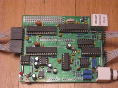
The boards above are the Futurlec opto relay 4 (10A @ 250VAC relays) - http://www.futurlec.com/Opto_Relay_4.shtml I don't think we'll be able to beat that at $14.90 per populated board (thanks for pointing these out earlier in the thread). It is nice that you can daisy chain 2 boards. There is also some proto area on them for the MCP23008. That way the relay box can have only 4 wires to it from the Hydra.

Hello Terahz, I just finished my Hydra and now I'm wondering if you're still using this Futurlec/American DJ relay board, I just purchased the relay boards and I'd like to see if you someone can help me with the Sketch and also the connections for the MCP23008?? I'm new to this and have a lot to learn... thx
 
Terahz must be on a sabbatical. Is anyone familiar with his firmware version 4.
I am trying to change the LED on off time and photo, no matter what I change they always come on at 11:30am
Any one no his trick?
 
Terahz must be on a sabbatical. Is anyone familiar with his firmware version 4.
I am trying to change the LED on off time and photo, no matter what I change they always come on at 11:30am
Any one no his trick?
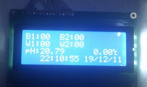
Hello TheShadow, I think you have to change the number 690 on the below line. For what I understood, the clock starts counting after 12:00am incrementing in minutes, for example 690min / 60min = 11.5 hours. So starting from 12:00am + 11.5hrs (690min) will start at 11:30am. so I think if you change the 690 to 540, it will start at 9:00am instead of 11:30am.
For the Blues (on line 59 from the HydraProd.pde):
uint16_t blueStartMins = 690; // minute to start blues. Change this to the number of minutes past midnight you want the blues to start.

Let me know if that works out, I haven't loaded on mine, since I'm still waiting for one part to come.
 
Last edited:
Terahz must be on a sabbatical.
I wish ...

I am trying to change the LED on off time and photo, no matter what I change they always come on at 11:30am
Any one no his trick?

The trick is called EEPROM. The first time you load the firmware, your eeprom is empty (or has other data in it). When the firmware detects it is not the right thing (Line 670: if (EEPROM.read(EEPROM_MAGIC) != 01) {) it writes the initial settings you have on top of your sketch and sets the magic number (Line 685: EEPROM_writeAnything(EEPROM_MAGIC, 01); ). Consecutive uploads will not write to eeprom (and thus change any settings), because the above EEPROM_MAGIC location will contain '01';

In order to change that, you can either use the remote and do it from the menu (the intended way) or change the value the above condition expects to say '00' (remember to do the same on both lines 670 and 685). If you change the EEPROM_MAGIC value it expects, ONLY the next upload will update the settings. That means, you have to change your start/end times, change the eeprom_magic value and THEN upload the firmware. Only then you will change the values that are actually used.
 
I wish ...

Hello Terahz!

I'm finally getting around to mounting my Hydra, and bought the same case as you have used.

How did you end up mounting your LCD to the case? I notice you didn't use screws and I like the clean look.

I don't have any fancy tools and don't look forward to cutting a rectangular hole in this thick aluminum either :)
 
Back
Top