NEW plumbing method for an ULTRA QUIET REEF TANK!!!! LONG !!!!

Ok...it makes sense now. I didn't quite get why we want to move the bypass vlv. I talked this over with some guys at work and now I get it. I won't actually move it, I'll just open it up. I'm going to just stick a new vlv in for the fuge. The only other thing that I was wondering about was starting this thing up for the first time. How hard is it to get the overflow levels dialed in while you are trying to get the desired flow through the fuge? What's a good starting point?

Powerman...when you had the siphoning, was it when you shut the pump off, or when it was running? Just curious.

Didn't see this... sorry.

Sounds good with the valve being left in place opened up.

It is not hard to get going. You want the regulation valve open wide to start and just start dialing it back. When you start restricting flow and the level in the overflow starts to rise you are in the ball park. You will have flow to the fuge with some air probably till the level in the overflow starts to rise and keep it out. Just set how much you want to the fuge, then adjust the level in the overflow with the regulation valve. Not too hard.

The only thing is to remember is if you change your flow to the fuge then you will have to readjust the overflow level. Now I just set my valve to the fuge and that is it. I never touch that. So the regulation valve gets a small tweak every now and then and thats it. Very rarely.

It was actually siphoning running on line. Just lowered my fuge level. It was quite unexpected. So I had to cut out the valve and place it downstream of the fuge tee and all was good. But ya... with the fuge being after the valve... well all you have is flowing water and two different levels of fluid and no air so the lower level will siphon out the till the levels are equal.

If you do not have the 1.5" gate valve yet... be sure to get threaded ends so you can reuse if necessary. That saved me $30 for that last redesign.
 
Thanks P-Man....I'll be sure to post when I get it running. Still have to gather some more parts for the return line. But thanks again for your help!
 
Wow, I finally got through this entire 6 year long thread. I have read every word of it and besides the siphon debate it was very informative. Cheers Herbie!

I recently moved into a 120 AGA from a 90 AGA and have done some extensive plumbing from the pump to a manifold that supplys water to my reactors and skimmer. I am running a reeflo dart and after reading this I wish I would have kept my Reeflo Blackfin 6000. Anyways the dart is just fine. I have everything done except I still have the two drains connected with flex hose and into a sock. I made my own dursos and it is very loud. When the wife says it's so noisy that she doesn't even want it in the living room anymore, I knew I had to do something and she loves my tank.

I have dual sumps ran from front to back on platforms and connected with bulkheads and 1 inch pipe. Should have gone with larger pipe to connect them but It's ok with the way it is now. The left side is the DSB and fuge seperated with two powerheads running for flow. I ran the plumbing from the pump to the left side but had lots of trouble keeping the two sumps water level the same. So now I have just two small pumps in there and the right side consists of the drains going into the sock and carbon reactor (yet to put back phosban reactor) and skimmer. This right side also has the dart connected that sits between the two sumps.

What I would like to do is incorporate the Herbie method but I have a question or two. Could I plumb the two 3/4 inch bulkheads together and then add the gate valve and leave the Dursos in as back up drains? Could the 3/4's handle all the flow from the dart?
Then I would of course go over the back with the returns from the dart.

Here's some pics. Since this 6 year old thread has so few pics, I'll try to keep up the pics rather than words. thanks in advance for your comments.


a451a295.jpg


2d96c0c2.jpg


3903efd3.jpg


5e9cfd44.jpg
 
TC...I saw that question asked before in this thread. The larger bulkhead (the one with the durso pipe) should be used for the main drain of the Herbie. If you think about it, it only makes sense to use the larger as primary and the smaller bulkhead as backup when you only have these 2 choices. I think widening the pipe in the overflow is a wise decision too.
 
Yup I realize that but if I crank up the dart all the way would I be in trouble if the one inch drains were to fail. In other words I guess I'll have to test it using the 3/4 inch and post results. I want max flow from the dart.
 
Hey that's a nice chart. I'll be setting this up next weekend. I'll play with it until I get it right. I figure the dart that's 3600 gph with the manifold and breaks, should be putting somewhere like 2000 gph or more to the tank with the pumpside gate valve fully open. Using the 3/4 as primary and the 1 inch as e-drains may not handle that kind of flow. Testing will tell.
 
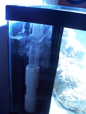
Well, I got it up and running. There's a little bit of a mismatch in my overflow levels. I think it's because I'm restricting flow through the fuge. OR...I don't have a true "T" coming off the drainlines. But I got it pretty well dialed in now. I ended up putting a thin coat of silicone on the 1" pipe and just pushed it into the b-head. I'm pretty sure it doesn't leak. I watched it for a while with the system shut down. (The PVC glue I have doesn't work on the black plastic bulkheads. It doesn't even try to hold.) The only problem I ran into was my main drain pipes needed to be cut lower. They were swallowing bubbles from the spillover of the overflow teeth. I started at 16.5 inches and knocked 5 inches off them. I just wasn't sure how much my sump could handle on a loss of power so I started a little long.

Since I wanted to use 1.25 pipe inside the overflows (I adapted up on both drains.), I was lucky enough to be able to use the 2 screens from both the dursos. They fit beautifully over 1.25 pipe. I just need to add screens to the back ups.

But what a major difference with a sump running smooth as silk. Ya gotta luv it. I appreciate your help with this p-man. Thanks again!
 
Looks like the mismatch in my 2 overflow levels was due to the teeth not being completely cleaned out. Algae and coralline appear to have a critical affect on the levels in the overflow box.
 
My tank only has one hole in the overflow. I have been battling the microbubbles and trying to find a solution and it seems using the Herbie method is the most logical solution. My thought is this, the one 1" hole in the bottom of the overflow will be the main drain, I can drain the tank and drill a second 1" hole in the back of the overflow for the emergency drain.

Will this work???
 
Sound like the bottom is drilled and you want to drill the back. Make sure it is not tempered. My tank could be drilled on the bottom, but the sides are tempered. BUT if you can drill it then that plan should work - assuming there is room in the overflow
 
Hey that's a nice chart. I'll be setting this up next weekend. I'll play with it until I get it right. I figure the dart that's 3600 gph with the manifold and breaks, should be putting somewhere like 2000 gph or more to the tank with the pumpside gate valve fully open. Using the 3/4 as primary and the 1 inch as e-drains may not handle that kind of flow. Testing will tell.

You want to use the 1" for main drains. The 3/4 is back up. That way you get as much flow as you need. The possibility of blocking the main drain 100% is remote. Therefore the need for the 3/4" to handle 100% flow is remote.

You can out do the overflow with your pump... they can only drain so much. How big is your tank and skimmer? 2000gph through a sump is a ton. There is only the need to supply a skimmer and a fuge.

EDIT: Sorry, read your post again. There is no need to recirc 2000gph througha sump for a 120g. A skimmer for your size may be processing 600gph and a fuge around 100-200. So 800gph is all you need. Anything over that is just moving water. You have plenty of room to dial back your pump and flow as much as you need through your overflows.

Also, there is no need for Durso "backups". The Herbie takes care of what the Dursos are attempting. Do a Herbie the way it is intended and call it good.
 
Last edited:
Is it possible to set up the Herbie method without pipes in the overflow? I will have drains coming from the end side glass with a 1 1/2" on bottom left and one on top right for emergency.
 
I think the problem would be an awful lot of water getting into the sump in the event of a power failure. It would be hard to stop a vertex from forming with little height above the top of the pipe. You could put a plate on top or other vertex stopping ideas, but without knowing a little more I can not make an educated opinion.
 
EDIT: Sorry, read your post again. There is no need to recirc 2000gph througha sump for a 120g. A skimmer for your size may be processing 600gph and a fuge around 100-200. So 800gph is all you need. Anything over that is just moving water. You have plenty of room to dial back your pump and flow as much as you need through your overflows.

Also, there is no need for Durso "backups". The Herbie takes care of what the Dursos are attempting. Do a Herbie the way it is intended and call it good.

Roger that. I was really just throwing different ideas out there. I realize that may be too much water movement through the sump. Once I get going I'll see what works best. The dart is cranked up pretty good right now so if I can achieve the same flow and have it quiet ++++++++++++!
 
Roger that. I was really just throwing different ideas out there. I realize that may be too much water movement through the sump. Once I get going I'll see what works best. The dart is cranked up pretty good right now so if I can achieve the same flow and have it quiet ++++++++++++!

Ya, I agree. I made all my return plumbing bigger to get the most flow. Well my Ehiem 1262 can easily out do my Herbie now. And I did everything to maximize flow from my overflow too. So I have it turned down a bit.

But ya... set your return to where the 1" drain is about maxed with a little regulation left over. Then you know you are about there and the 3/4" should catch anything left over. Again.... 100% blockage would be hard. I passed a snail through my gate valve... but that was before I had proper screens on my overflow. So with proper screening, you should never have a problem.... I have not since.

That dose not mean that the emergency drain is not needed though. Everynow and then things will get out of whack and the emergency will pick up the slack. Sounds like you got things on the right track.
 
I think the problem would be an awful lot of water getting into the sump in the event of a power failure. It would be hard to stop a vertex from forming with little height above the top of the pipe. You could put a plate on top or other vertex stopping ideas, but without knowing a little more I can not make an educated opinion.

The tank is a 65G and setup with a divider overflow. I am going with a peninsula style tank and wanted maximum in tank volume. The overflow is only holding 3.3 gallons of water at the max.
 
Tek,

I think what you are saying is that you have two bulkheads in the side of your tank and a glass over flow. Got a picture? What is the height distance between the 2 overflows? The herbie varies some, but if you have 6 inches you should be ok. If I understand you then no you do not need pipes. The main drain in a standard herbie can be run pipeless, adjust the height of the water using the valve. You could then add a pipe up to the water (a little less) in the overflow and since the head pressure does not change the height in the over flow does not change. The emergency is some distance above that. If flow stayed constant it would not matter too much, but evaporation, growths, etc affect the flow so a little more height before it hits the emergency is a little better.
 
Here is a pic of the overflow with 1" bulk head. If I drill the back, where and what size drain hole would be recommended? Keep in mind this is a 40g breeder with 20g long sump and BlueLine 40 hdx return pump.
 

Attachments

  • 437.jpg
    437.jpg
    50.4 KB · Views: 8
Back
Top