Ozone use

Hi Boomer,

Yes, Avast Marine has their mutiny ozone reactor. I know I found another manf. in my searches but I cannot seem to locate them tonight.

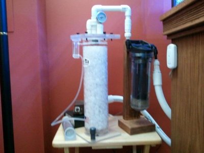
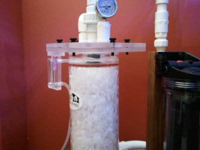
There is a youtube video, 9rHXWBpqdTE : "Trial Avast Mutiny Ozone Reactor" that show the system in operation. In this video they do not have carbon in the carbon reactor, but you can see it fills with air.
This video shows the same system with the carbon reactor filled with carbon but yet still trapping air under pressure; jJyxprkCp6g "Ozone reactor's carbon postfilter"

This system is designed to account for the backpressure you mention above. The system does not bind with air, but burps itself constantly. This burping will make a mess at the point of discharge but this could be taken into consideration when setting the system up.

This air filled carbon reactor has enough dwell time to minimize/eliminate the ozone in the air and still filter the effluent as it dribbles past.

What are your thoughts on the system? I am a noob to ozone. I've learned alot from this thread and other research but still am a sponge. I'll be using 50-75mg/hr with an oversized carbon reactor. I am pretty confidant from the research this solution will work for me w/o ozone smell in the room.
 
What they really have there is two ozone reactors, R #1 is for ozone and #2 is for GAC. The water inlet of both is at the Nine-O'Clock position and the outlet of both is in the center. There is no burp tube in this reactor but the R3#2 outlet acts as both a water and air discharge. It is a nice looking unit and works this way.


1. Water and air enters R#1 @ Nine-o'clock through the same port and falls to the drop plate, where it drips down to the bottom. Basically zero Ozone reactors mix water and air like this. Normally the water enters through its own port inlet and the air enters through its own port inlet, there is none of this mixing on the same inlet. Take note of the air-inlet nipple on this reactor.

http://www.marinetechnical.com/page6.html

At the Three-O'clock position is the air inlet and at the Six-o'clock position is the water inlet. The burp-tube is in the center column of the reactor tube, just past the half-way mark at the Six-o'clock position. This is the burp tube line that controls the water level of the reactor so it is the same. This Avast reactor has no water level control and has no pressure gauge to tell you what the internal air pressure of the reactor is.

In more advanced Ozone reactors, like mine, which are just not out there any more, the air enters the reactor near bottom just above the second drip plate in the bottom of the reactor, with a 90 degree elbow inside the reactor. So, all the air blows up as the water is coming down, thus creating counter-current exchange, which is much more efficient. Mixing the air water like they do is the least efficient way but yes still does work. So, as you can see there are 3 ways to do this, mine, MTC reactor and theirs.

This is mine, the early version:

O2-3Reactor2001.jpg


O2-O3Reactor002.jpg


2. So, how does the Avast really work, as far as internal water level, the WRONG way. Since there is no water level control, via a burp-tube or a mechanical or electronic float switch to control water level, you can never control a proper water level with this unit. The reactor will either fill up with water in time or air in time. It is usually go with the air in time. So, at some point in time, like every few min or a hr or so the internal air level will reach the water outlet tube. When that happens all the air in the reactor will evacuate the reactor and go out the water outlet tube, often accompanied by a big bang :). The reactor has now had a sudden drop in air pressure from loosing all its air. So now, the water level begins to rinse in the reactor again but at the same time the air pressure builds back-up also and the reactor runs fine for a few min or hr again and then repeats this. Not very efficient on two counts but yah is still works. The video does not show this massive air evacuation and I see no water level control of any kind. Evacuation of all the air out at once is NOT a water level controller. The water level is suppose to be as constant as possible, which can be keep within reason with a burp-tube, mechanical or electronic float switch. An even more efficient reactor, no longer out, is where there is no media at all. We used expensive industrial water atomizer nozzles, where the inside of the reactor looks like it is filled with fog tumbling around.
 
I agree, the Avast solution is a step away from others. I understand it not as efficient as possible, the fogging or high pressure water column dissolving methods would be far superior. I believe the Avast works well enough as it uses the venture to first mix, then a 3-4psi air filled reaction chamber to further dissolve O3. IMO the results should comparable to pumping Ozone into a skimmer venturi but allow for a GAC postfilter which a skimmer does not. Also being pressurized, I can locate the Ozone reactor at or below a sump water line while maintaining proper stable water level in the reaction chamber.

In the Avast there are no big bangs, just the numerous tiny constant ones. These are frequent enough to balance themselves creating a stable reaction chamber resulting in constant air pressure and water level. The discharge tube is cut to have about a ½” long “V” at the bottom. I believe this is the mechanism to prevent the mass evacuations. The air and water can balance themselves by burping themselves over the V in the tiny amounts. All of this assumes the incoming water column and air pressure fall within the designed range to create the stability.

My actual intent for the first post was not to get too far into the operation of the Avast O3 reactor but more about the GAC postfilter.

Your big bang was the actual intent of my first post. I am not fond of cleaning the open style GAC reactors, I prefer the ease of cartridge style. With the cartridge style, there is no open bed of GAC held in place by media plates but a central canister surrounded by open chamber. I am not sure it this design would allow for a similar air balance as created in the Avast GAC reactor. I am afraid of the big evacuations resulting in bangs but was curious to see if anyone has tried such a solution in any of their pressurized ozone reactor GAC chambers.
 
I believe the Avast works well enough as it uses the venture to first mix, then a 3-4psi air filled reaction chamber to further dissolve O3

Well, I'm sure it does an OK job but my points is it could be done better with little cost increase. It is not the mixing of air and water you are trying to achieve it is to have proper internal air-pressure. And the purpose of media is to get the water to a thin film layer on that media, which allow O2/O3 to be driven into the water more efficiently. It is the air pressure that drives in the O3/O2. 3- 4 psi is low and needs to be above 5 psi. We have run them a high as 20 psi. Roughly, every 2 psi drives in 0.25 ppm DO. One could also use a O2 Saturator Cone to do this and many do in the aquaculture world.

MO the results should comparable to pumping Ozone into a skimmer venturi

It will be better than any skimmer, all reactors are. Skimmers have no internal pressure.

The discharge tube is cut to have about a ½" long "œV" at the bottom

The discharge tube is cut to have about a ½" long "œV" at the bottom[/b]

OK, that will work but you still have no real control. A true "burp-tube" is a small air line nipple that enters just above the discharge tube. An air-line then runs to the sump where a needle valve is then attached to the tube to control the water level even more precisely, where said air burps out of that end-line into the sump. What you do with that end-line is a choice, below the water above the water or above the water with a baffle fitting.

All it in all it is a nice looking unit and looks like a well built unit it just needs a fix. It would be better to have a burp-tube running to the GAC reactor from the O2/O2 reactor.

I prefer the ease of cartridge style.

I understand that

I am afraid of the big evacuations

I think we can get around that, just run a burp-tube with a needle valve to the cartridge where the water enters the cartridge. This would allow very small amounts of air, from the reactor, to leak into the GAC reactor water and mix with it. The GAC cartridge does not be need to be filled with air. Both the incoming air and water will be scrubbed by the GAC before it leaves the cartridge. This can be done by the ozone reactor water gravity feeding the GAC cartridge which then drains into the sump and the rate of water air-discharged to the sump form the GAC reactor could be tuned with a ball-value and a DIY baffle fitting, if needed. This would stop any unwanted spray effect that may take place.
 
Great. You have provided some of the info I have not been able to find.


needs to be above 5 psi. We have run them a high as 20 psi…. every 2 psi drives in 0.25 ppm DO
I could find nothing telling me how much internal pressure is typically run in O3 reactors for fish tanks. I was able to find some similar O2 absorption numbers but nothing for O3. With your psi numbers I no longer need to know.

OK, that will work but you still have no real control.
I agree. The end user gets the operation the reactor was engineered to, tailoring this more to a person who does not want to fiddle with anything. I don’t fit that profile, but the build quality and price for their medium size reactor as a DIY build kit is very hard to beat.

I think we can get around that, just run…
Thank you. I don’t have enough time to fully digest this at work but I will understand it in detail.


For my first test I’m planning to hook the reactor up as built, connecting to a GAC cartridge I already have and see how the system operates. I’m wondering how the canister will react to a flow from the different directions. I’ll hopefully be able to get this accomplished over the weekend. Seeing the system operating should will give me some good experience to figure out what the next steps are. Including the addition of a good pressure gauge.

I really appreciate the help and details, your description should get me to the efficiency I need.

Josh
 
I could find nothing telling me how much internal pressure is typically run in O3 reactors for fish tanks.

It is pretty much the same for O2 as it is O3 as both are gasses. For O3 it is more the dosage, which the std is 0.3 - 0.5 mg / net gal. That means the dial setting on your ozone unit. If you have say 100 net gals the dial should be set at 100 x 0.3 - 0.5 , or a dial setting of of 30 - 50. Most is pretty much dependent on the ORP you are trying to achieve which should not ever exceed , 450 mv. 400 mv is a good number to shoot for. For modern skimmers it should be much less, due to short dwell time, otherwise these levels may cause more foam collapse. For older type columnar skimmers, with longer dwell time you can run it this high and get increased skimming.


pressure gauge.

Yes, as the higher the pressure is the more O2/O3 is driven into the water. Running a pressure of 2-3 psi is almost useless. I'm sure you have heard that at higher elevations the O2 is less than at lower elevations. Most reef tanks are not saturated with O2 at sea-level, despite most think they are and O2 test kit will prove my point and this is the reason behind a O2 reactor, not that one has to have one. The reason behind the O3 reactor is the same.

If one looks at a coral reef the O2 is pretty much saturated at 6.6 ppm @ 77F. Many reef tanks may run in the low 6's or high 5's. So, buy running a reactor we can achieve that 6.6. If we now look at Denver @ 5,000 ft elevation and a reef tank at saturation it will be 5.5 ppm and that is 1 ppm below which the coral reefs are and we may want to rise it with a O2 reactor. If the reactor is running at say 6 psi the O2 will increase to about 0.75 ppm and now we are like 6.25 ppm, much better than that 5.5 ppm. But more that level that Denver tank has is more like 5 ppm so now we are more like 5.75 with that reactor. We do not want tanks running lower than 5 ppm O2. And I will add that moderate to heavy stocked FOT are often lower than reef tanks by 1 ppm. I have measured many in the mid to high 4's at ~ sea level - 1500 ft. And will add it is not as much of a deal with a FOT as it is a reef tank. The real issue with these low levels in FOT is if something happens at night or you lose power, fish will die quickly.


Keep me updated
 
That is more great info.

I did not think of the increase in usable DO as a result of running O3 reactor, but I should have. I actually would have expected higher average DO; the skimmer, the powerheads and large surface area to have put the DO into the 8ppm range. Studying ecology, in younger lakes we expected 8ppm and 5-6 range in active older silt laden lakes. These were averages and varied at depth, temp, time of year but were good general starting points to use. If we had artificial mixing I could see numbers above 10, I thought the reef tank would be higher.

I am painfully aware of evaluation affecting O2 levels, I need to rejet my holley carb twice a year for temp and needed to much more when living in Denver/Broomfield.

After some thought, I want to redesign the return plumbing so it’ll be a few days before I get the reactor up and running but I will definitely post back with the results. I also post with the final solution and results.
 
The powerheads and large surface area to have put the DO into the 8ppm range. Studying ecology, in younger lakes we expected 8ppm and 5-6 range in active older silt laden lakes

Not even :D that is fresh water and the salt in seawater drops the DO substantially below FW at the same temp and elevation.

Studying ecology, in younger lakes

Part of my schooling was in Limnology years ago and Wetzel's text is only a arm reach away, as are another 1/2 dozen on stream, lake ecology texts and 6 others just on FW chemistry. I live in the land of lakes and streams:D

FW DO Sat @ 25 C, 0 ft. elev. ( 29.92 in. Hg) and 0 Salinity = 8.288 ppm

Seawater DO Sat @ 25 C, 0 ft. elev. ( 29.92 in. Hg) and 35 ppt Salinity = 6.617 ppm.

That is a 1.67 ppm drop in DO just due to Salinity and since most reef tanks are warmer than 25 C it will be a even higher drop, on the order of 0.4 ppm lower in DO @ 82F. And if a low pressure weather front rolls in even more of a drop. A 1 in. drop in pressure will drop the DO another 0.2 ppm, at the same temp, Salinity and elev..
 
Boomer you are a person of many skills and much knowledge. Do you have any books you've published? :) I've built a good note book from just your posts, added to other's informative posts and...

I started research tonight and found the error in my inital DO thoughts. It's nice my memory served me correct with FW DO saturation, it's been a decade since I've touched the topic.

I've got a decent start on the plumbing redesign, it'll be a couple more nights and I should have the O3 reactor up and running for its trial.
 
Nope, me no write books, articles or do talks, it is just not my thing to do that.
 
Well buddy now you see the real deal I was taking about on the phone. You can see the descending air line that goes into the bottom just above the button trickle plate so the air goes up as the water comes down for counter-current exchange like the old columnar skimmers. The water level is kept just below that bottom trickle plate and the ascending water enters the center tube just below that plate and goes up the center tube as the effluent and then to a descending GAC post Ozone filter via gravity feed, which can dump in the tank or sump. This big beast is 32" in by 6 " with a 3/4 center tube effluent. The effluent and influent elbows on top are 3/8 " internal diameter.
 
Keep me updated

I was able to get the first test completed. I am suprised on how well the first setup has worked.

To provide a little more info on my setup; I am running a reeflo snapper as my return and O3 feed pump. The pump does not deal well with head pressure. To negate this I ran 1" dia and short lenght plumbing from the pump to the O3 reactor. This still was not enough and I had to remove the stock venturi. I replaced it with a 1" T and inject the O3 via a nipple. This T and nipple are a few inchs upline of the reactor chamber. I plumbed the reactor output to a GAC canister style reactor w/ 3/8" ports. I also added a pressure gauge to the chamber.
I run the GAC reactor using the normal flow direction. The area in the chamber oustide of the GAC canister fills with air and the air gently bubbles under the lip of the canister. The GAC canister stays completly fills with water.

The results; the reaction chamber runs at 2.5psi with 2sfcm O3/O2. There is no noticable burping at the output in my sump. I'll watch the ORP and record how much of an increase I get as compared to my previous setup.

My next step it to order a jumbo GAC canister reactor w/ 1/2" ports. This should give me much more flow. Currently I am only able to get about 250-300gph due to the reeflo. With the increase in flow I am hoping for 1psi or more increase in chamber pressure. When I removed the stock restrictive venturi I gained 1psi and aprox 150gph flow.

I'll post back after the next test, it should be operational next weekend. I'll also post some photos or video once I like the results.
 
OK, who's reactor are yoiu using ?

Edit roomer:

Because you are feeding the air form the top and have poor air-water mix what a CC does give, where there is no surplus over-head ozone trap.

Too: Because you are feeding the air form the top and have poor air-water mix what a CC does not give, where there is no surplus over-head ozone trap.
 
Last edited:
OK, who's reactor are yoiu using ?

The Avast reactor which we had been discussing. You had asked to keep you posted in reply #306, I'm reporting back with results.

Too: Because you are feeding the air form the top and have poor air-water mix what a CC does not give, where there is no surplus over-head ozone trap.

You lost me here. What is a CC?
Also, what is a surplus over-head ozone trap? Are you refereing to an seperate open chamber above a media bail?
 
I'm reporting back with results.

Yes, but did not realize it was a Avast you had and thought it was another reactor you had looked at and its operation was of interest to you.


What is a CC?


Counter-Current exchange

open chamber above a media bail?

Yes and even above the top drip plate where it enters. The water entering the drip plate will have very short contact time with the ozone as it leaves the drip plate. Some Ozone may also accumulate under that plate. In CC air enters above the bottom drip, where the air is directed upward as the water descend. As the air ascends upwards it will bounce off the upper drip plate and then descend back down. So, is is like two air -water mixings, one on the way up and one on the way down. So, it ends up where you really have both Countercurrent and Concurrent in a O2/O3 reactor.

Here is one example of CC.

5767294.png


Water enters at 112 and air enters at 116 and water leaves at 114 and the stripped air ( degassed air) vents out of 118. These are what are called a Degassing Towers or Air -Strippers. They are used in many public aquariums and industrial plants. Many Trickle-Filter work this way.

Here is another one of CC and CnC
600px-Exchangerflow.svg.png


The lower the internal air pressure is the more you want it to be CC & CnC. Lastly, is the reason behind the media and the type of media. The media allows the water to flow over the media producing a thin layer /coating of water on the media which makes it much easier for O2/O3 to enter the water. The shape of the media and its surface area and how it can or can not sheet over the media is a big issue in the field of Mass-Transfer Chemical Engineering, which a O2/O3 reactor is. This is why media like the Advanced Dupla-Bio-Balls and media like Bio-Bail ( saved PVC) are used in O2/O3 reactors. Bio-Bail should be the preferred choice, especially at lower internal air pressure. We always want to try and achieve maximum efficiency.


Forgot about this 2sfcm O3/O2

Is meaningless, as it is a flow rare and says nothing about the concentration in that flow rate. Your O3 unit should be set on the dial to ~ 0.3 - 0.5 mg / gal. If it is 100 net gals then 100 x 0.3 - 0.5 or the dial set at 30 - 50. This is only a good starting point, it is not set in stone. Many Public Seawater Aquairms run it 10 x less than that.
 
Ok so Ive been reading through this thread and a lot of this still confuses me.

To start I have a 420g system which I would like to add ozone and a reactor to.

Boomer do you have a diagram of how exactly that reactor you have pictured above works? Ive found plenty of diagrams on how to hook them up, but no good ones for how to actually make a decent one.

I understand pressure makes a difference in the O3 uptake, but is it really all that important when considering the small scale of a home aquarium? I mean if you can get a cheap 400-600 mg/hr generator and make a 2-3g reactor that should more then cover even a very large system right?

I was planning to do something similar to what you have pictured there, with a drip plate over bio balls and the ozone inlet near the bottom. Then run the ozone/water mix through a carbon reactor.

An other question, can I simply use a larger carbon reactor and use that as the carbon for the whole system or should they be kept separate?
 
thought it was another reactor you had looked at
After looking over the options I did decide to go with the Avast. After your help and the reading, I think their's is a good starting point at worst and just what I need at best.


Counter-Current exchange
Thank you for the info on the CC. There is a defeciency in the design I am using as it does not allow for CC. By choosing the chamber size I did as well as trying to get the internal pressure up to the 5-8psi range I'll would hope to be able to gain enough saturation to acheicve the desired effect. I can always convert it to be a CC but I'll wait to see how it performs as designed.


and even above the top drip plate where it enters.
This one does have a top chamber above the drip plate. See attached.


We always want to try and achieve maximum efficiency.
I agree. Adding to this, build quality is also requirement. I'm also figuring in cost, so that the best effeciency per dollar of quality product is the net result.


Forgot about this 2sfcm O3/O2
It was more of a data point. I am running .3mg per gallon per the knob on the generator, but w/o a air dryer the actual output is lower and more of a guess. The final solution will have an air dryer.
After learning about the D.O. of seawater, I'm also trying to incease my saturation levels as an added benefit.


All be it fuzzy, a picture of the test rig.
 

Attachments

  • 2011-10-23 16.01.30.jpg
    2011-10-23 16.01.30.jpg
    43.3 KB · Views: 7
  • 2011-10-23 16.01.39.jpg
    2011-10-23 16.01.39.jpg
    38.7 KB · Views: 7
An other question, can I simply use a larger carbon reactor and use that as the carbon for the whole system or should they be kept separate?

I'll be implementing as a whole system GAC, as only my ozone generator will be shut off when I reach my desired ORP. I will leave water flowing through the reactor and carbon chamber at all times the return pump is running. I'll mainatin my smaller GAC reator as a second or backup unit for any future needs.

I may be off base on implementation. From my understanding I think this will be viable and have less maintenance.
 
Ender

Boomer do you have a diagram of how exactly that reactor you have pictured above works?

First, what diagram are you talking about, give post number.
 
Back
Top