toiletkavorka
New member
Ok this is my first ever tank design but after gathering info non stop for a month I made this...and it took me all day cause i had to do it research some more and learn how to use google sketchup errr anyways i hope it clears things up:
Also any help on how to put up a pic/avatar of my own would be awesome.....
Things I am still working out/worried about:
1) How to connect the powerheads to the bulkheads and the one bulkhead to the hydor flo
2) fearing that the fuge design i have done will have water coming through the outake slots.....now i got a PH pumping water into that chamber and i made the slots 1 inch shorter then the intake in the hope water would goin those before they even reached the outake slots ........but i am still not sure if this is feasable or if i will have water flowing back through the slots???
(All below is intellectual property of yours truly and should not be copied or duplicated without express consent...lol...I always wanted to say that....well it is not copyrighted and i most likely would notmind if you used it but it would just be nice to ask eh??)
CUSTOM TANK DIMENSIONS
(Where applicable all measurements in a: L x W x H fashion)
Tank Bottom: 0 .5â€Â
Tank Walls: 0.5â€Â
Tank False Wall: 0.25â€Â
Baffles: 1st 0.125†2nd 0.25†3rd 0.125†Fuge Box: 0.125â€Â
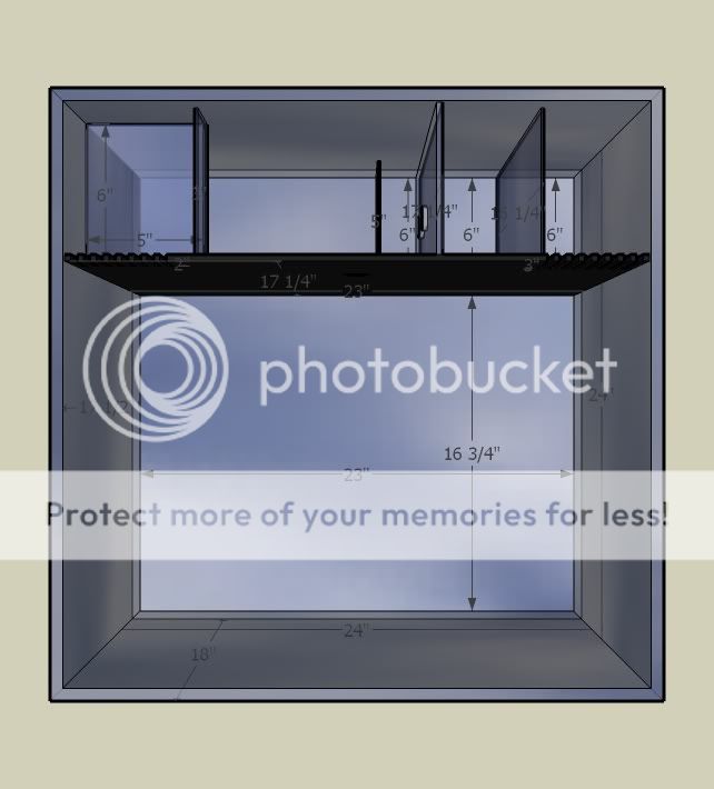
Full Tank (Outside measurements): 24†x 24†x 18†(38.9 Gal.)
Full Tank (Inside measurements): 23†x 23†x 17.5†(34.6 Gal.)
Display Area (Inside measurements): 23†x 16.75†x 17.5†(24.8 Gal.)
Full Back Area (Inside measurements): 23†x 6†x 17.25†(10.3 Gal.)
False Wall: 23†x 0.25†x 17.25â€Â
First Chamber (Inside measurements): 4†x 6†x 17.25â€Â
First Baffle: 6†x 0.125†x 16.25†(allows for 1†clearance from top of false wall)
Second Chamber (Inside measurements): 4†x 6†x 17.25
Second Baffle: 6†x 0.25†17.25†(allows for no clearance from top of false wall and extra width to accommodate the baffle drilling)
Third Baffle: 6†x 0.125†x 5†(This baffle is spaced 2†from the second Baffle)
Third/Fuge Chamber (Inside measurements): 14.5†x 6†x 17.25†(6.5 Gal. 18.77% of total display area)
Fuge Outtake Protection Box (Inside measurements): 5†x 6†x 3†(1†clearance from top of the false wall)
Intake Slots: 0.25†x 0.25†x 3†(right side of tank leads into first chamber spaced 0.25†apart)
Intake Slots Area (L x W = A): 3†x 0.25†= 0.75 Square Inches x8 slots = 6 Square Inches
Outtake Slots: 0.25†x 0.25†x 2†(left side of tank leads from the fuge chamber spaced 0.25†apart)
Outtake Slots Area (L x W = A): 2†x 0.25†= 0.5 Square Inches x 8 slots = 4 Square Inches
½†Double Threaded Bulkhead Area (Pie x Radius x Radius = Area): 3.14 x 0.25†x 0.25†= 0.19625 Square Inches
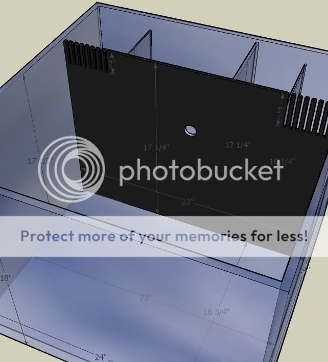
1st Double Threaded Bulkhead Placement (Top one on Second Baffle wall): 3â€ÂL x 6†H (1/2†Bulkhead needs 1.125†hole drilled with a radius of 0.5625â€Â)
2nd Double Threaded Bulkhead Placement (Bottom one on Second Baffle wall): 3â€ÂL x 3†H (1/2†Bulkhead needs 1.125†hole drilled with a radius of 0.5625â€Â)
Space between 2nd and 3rd Bulkhead Holes: 1.875â€Â
3rd Double Threaded Bulkhead Placement (2/3rds up False Wall): 11.5â€ÂL x 11.5†H (1/2†Bulkhead needs 1.125†hole drilled with a radius of 0.5625â€Â)
EQUPMENT DIMENSIONS AND STATS
Tunze 9002-
•Recommended for aquariums 10 to 52 gal of salt water
•Dimensions: 4.9" L x 2.1" W x 13.3" H
•Immersion depth: approximately 7" to 8.6"
•Skimmer cup volume: 0.79 gal
•Power consumption: 10W
Maxi Jets (Dimensions do not include attachments or suction cups)
Connections: 3/4" ID hose fits inlet / 1/2" ID hose fits outlet
400 5W 106gph 3.5" L x 2" W x 3.00" H
600 7.5W 160gph 3.5" L x 2" W x 3.00" H
900 8.5W 230gph 3.5" L x 2" W x 3.25" H
1200 20W 295gph 3.5" L x 2" W x 3.25" H
OK and here is the pics:
Front:

side:

side:

back:

back diagonal:

top:
top diagonal:
NOW i did not yet insert the powerheads but they will be an MJ 600 and a mj 1200 and theywill be draining water out of chamber 2 after it comes through the eggcrate mod with the filter floss and chemical (purgien or chemi pure) it will at this point also have run through the tunze 9002 in chamber 1 so it will be clean water going back into the tank via the hydor or into the fuge......
I hope this makes sense now and is doable
again all criticism welcome...
Cheers
MAIN SITES USED
calculations from: http://www.drhelm.com/aquarium/areajava.html
measurements at: http://www.marinedepot.com/ps_AquariumPage..._micro-jet.html
and
http://www.tunze.com/149.html?&L=1&...r_tunzeprod_pi1[predid]=-infoxunter050
Influences:
Finnex tank back design:
http://www.finnex.net/catdetail.php?idcategory=16
CPR Aquafuge:
http://www.cpraquatic.com/pdf/aquafuge.
Also any help on how to put up a pic/avatar of my own would be awesome.....
Things I am still working out/worried about:
1) How to connect the powerheads to the bulkheads and the one bulkhead to the hydor flo
2) fearing that the fuge design i have done will have water coming through the outake slots.....now i got a PH pumping water into that chamber and i made the slots 1 inch shorter then the intake in the hope water would goin those before they even reached the outake slots ........but i am still not sure if this is feasable or if i will have water flowing back through the slots???
(All below is intellectual property of yours truly and should not be copied or duplicated without express consent...lol...I always wanted to say that....well it is not copyrighted and i most likely would notmind if you used it but it would just be nice to ask eh??)
CUSTOM TANK DIMENSIONS
(Where applicable all measurements in a: L x W x H fashion)
Tank Bottom: 0 .5â€Â
Tank Walls: 0.5â€Â
Tank False Wall: 0.25â€Â
Baffles: 1st 0.125†2nd 0.25†3rd 0.125†Fuge Box: 0.125â€Â
Full Tank (Outside measurements): 24†x 24†x 18†(38.9 Gal.)
Full Tank (Inside measurements): 23†x 23†x 17.5†(34.6 Gal.)
Display Area (Inside measurements): 23†x 16.75†x 17.5†(24.8 Gal.)
Full Back Area (Inside measurements): 23†x 6†x 17.25†(10.3 Gal.)
False Wall: 23†x 0.25†x 17.25â€Â
First Chamber (Inside measurements): 4†x 6†x 17.25â€Â
First Baffle: 6†x 0.125†x 16.25†(allows for 1†clearance from top of false wall)
Second Chamber (Inside measurements): 4†x 6†x 17.25
Second Baffle: 6†x 0.25†17.25†(allows for no clearance from top of false wall and extra width to accommodate the baffle drilling)
Third Baffle: 6†x 0.125†x 5†(This baffle is spaced 2†from the second Baffle)
Third/Fuge Chamber (Inside measurements): 14.5†x 6†x 17.25†(6.5 Gal. 18.77% of total display area)
Fuge Outtake Protection Box (Inside measurements): 5†x 6†x 3†(1†clearance from top of the false wall)
Intake Slots: 0.25†x 0.25†x 3†(right side of tank leads into first chamber spaced 0.25†apart)
Intake Slots Area (L x W = A): 3†x 0.25†= 0.75 Square Inches x8 slots = 6 Square Inches
Outtake Slots: 0.25†x 0.25†x 2†(left side of tank leads from the fuge chamber spaced 0.25†apart)
Outtake Slots Area (L x W = A): 2†x 0.25†= 0.5 Square Inches x 8 slots = 4 Square Inches
½†Double Threaded Bulkhead Area (Pie x Radius x Radius = Area): 3.14 x 0.25†x 0.25†= 0.19625 Square Inches
1st Double Threaded Bulkhead Placement (Top one on Second Baffle wall): 3â€ÂL x 6†H (1/2†Bulkhead needs 1.125†hole drilled with a radius of 0.5625â€Â)
2nd Double Threaded Bulkhead Placement (Bottom one on Second Baffle wall): 3â€ÂL x 3†H (1/2†Bulkhead needs 1.125†hole drilled with a radius of 0.5625â€Â)
Space between 2nd and 3rd Bulkhead Holes: 1.875â€Â
3rd Double Threaded Bulkhead Placement (2/3rds up False Wall): 11.5â€ÂL x 11.5†H (1/2†Bulkhead needs 1.125†hole drilled with a radius of 0.5625â€Â)
EQUPMENT DIMENSIONS AND STATS
Tunze 9002-
•Recommended for aquariums 10 to 52 gal of salt water
•Dimensions: 4.9" L x 2.1" W x 13.3" H
•Immersion depth: approximately 7" to 8.6"
•Skimmer cup volume: 0.79 gal
•Power consumption: 10W
Maxi Jets (Dimensions do not include attachments or suction cups)
Connections: 3/4" ID hose fits inlet / 1/2" ID hose fits outlet
400 5W 106gph 3.5" L x 2" W x 3.00" H
600 7.5W 160gph 3.5" L x 2" W x 3.00" H
900 8.5W 230gph 3.5" L x 2" W x 3.25" H
1200 20W 295gph 3.5" L x 2" W x 3.25" H
OK and here is the pics:
Front:
side:
side:
back:
back diagonal:
top:
top diagonal:
NOW i did not yet insert the powerheads but they will be an MJ 600 and a mj 1200 and theywill be draining water out of chamber 2 after it comes through the eggcrate mod with the filter floss and chemical (purgien or chemi pure) it will at this point also have run through the tunze 9002 in chamber 1 so it will be clean water going back into the tank via the hydor or into the fuge......
I hope this makes sense now and is doable
again all criticism welcome...
Cheers
MAIN SITES USED
calculations from: http://www.drhelm.com/aquarium/areajava.html
measurements at: http://www.marinedepot.com/ps_AquariumPage..._micro-jet.html
and
http://www.tunze.com/149.html?&L=1&...r_tunzeprod_pi1[predid]=-infoxunter050
Influences:
Finnex tank back design:
http://www.finnex.net/catdetail.php?idcategory=16
CPR Aquafuge:
http://www.cpraquatic.com/pdf/aquafuge.
