WIRING the ELN-60-48D

SnowManSnow

Member
Hi guys I'm pretty sure I know what to do here, but I just want some confirmation before I screw anything up.

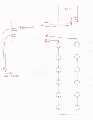
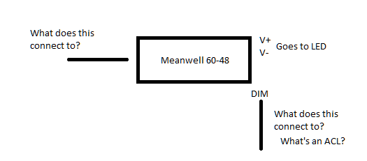
ON the 48 D I have AC IN with a brown and blue wire. These Go..... ?
Does it matter which I wire to which on the plug?

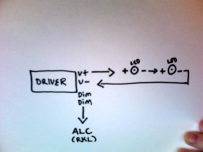
I also have a V+ (red) and a V- (black) .. in detail where do THESE go?

I also have a DIM + (blue) and a DIM - (white)... same as above please.

AS A NOTE I will be using the ALC with my RKL on this project.

________

Internal trim. I've seen several references to adjusting this before any power goes through the driver. What do I do with it? Turn all the way down? (counterclockwise)... and then back it back up? Just a little confused as to WHY ..

Thanks.
B
 
The AC wires that go into a plug dont matter which way.

The V+ goes to a + on the LED the - of that LED goes to the + of the next LED etc.

The - of the last LED in the string goes to the V- of the driver.

The two DIM signals go to your ALC dimming channel.

Set the dimming output of the ALC to max (+10V) then set the meanwell max current to what you want the LEDs to run at. DO NOT turn on the driver until you have turned the internal dim pot counter-clockwise all the way or you will blow the string when you turn it on the first time.

THEN adjust upwards. To measure the current properly you need a digital Multi Meter placed inline on the LED string to read the current.

Stu
 
Isn't the polarity important for the input simply because if the case is grounded by reversing the wires you actually make the case hot?
 
This driver is meant to be assembled into a higher level assembly. I think the spec even says that this is NOT meant to be an end-product.

There is no ground on the driver and the case is plastic. It would be up to the DIY mechanic to ground the outer case separately.

Bottom line is that it doesn't matter which AC lines you connect to what but if it makes you feel better, AC-L is the line (hot/black) and AC-N is the neutral/white.
 
OK ...
so wire up the dvds.. + on one to the - of the next in line and so forth... The last - goes back to the driver. ok

as far as powering up...

Should I set the trim inside the driver BEFORE I hook it to the array?

Plug in hook to ALC then adjust the internal pot so that I get a MAX of 10v between the + and -..

then hook to the lights in the way described above.

B
 
I thought the max current was 10v?

what DO I want the max current to be... if not?

B

Current is measured in amps :confused:. The max current should be 1a when 10 Volts DC is put out by the ALC.
 

Attachments

  • 1235cn_20100509_08432601.jpg
    1235cn_20100509_08432601.jpg
    22.5 KB · Views: 2
To help clear it up. The driver you have has TWO ways to adjust the power that the LEDs are running at (actually three, but the third - voltage limiting - doesn't come into play when it's run as a constant current LED driver.)

First, there is the internal trimpot. Think of this as the max. limiter for current provided to the LEDs. The trimpot sets the max current (amps) your LEDs will run at. You adjust this internal pot simply by turning it with a screwdriver and reading the CURRENT (amps, not volts) on the output string, i.e. in series with the LEDs.

Second, there is the external dimming signal, connected to the external wires. This external circuit allows you to dim DOWN from the max current set by the internal pot. You control this function by providing a voltage signal to these wires, between zero and 10 volts. The LEDs aren't actually running at this voltage, it's merely a signal. The driver translates the signal into a percentage of the current set by the internal trimpot.

So, when your external signal source (ALC, whatever) is providing a 10v signal, your LEDs aren't running at 10v, they're running at 100% of the current limit set by the internal pot.

The internal pot is a set and forget kind of thing - you configure it when you install the system, and then you likely won't touch it again. Depending on your plans and which LEDs you're using, typical values might be between 700 and 1000mA.

The procedure Stu suggested above is 100% exactly what I would suggest. Turn the trimpot all the way down (counter clockwise). Wire everything up, with your external control signal set at 100% (i.e. 10v). Put a multimeter set to measure amps in series with the LEDs. (make sure it's well connected, you don't want loose connections!) Plug the whole thing in, and measure the current. Leaving your external signal set to 10v (100%), adjust the internal trimpot upwards until you get the current you want, which will be between 700 - 1000mA for most people. Then, unplug the driver, remove the multimeter from the circuit, close the circuit, and you're ready to go.
 
For some of us it takes baby talk

THANK YOU.

and to make sure I wire correctly... see the below diagram...

b
 

Attachments

  • LCD Diagram 1.jpg
    LCD Diagram 1.jpg
    21.2 KB · Views: 4
The 10v wall wart discussed in this thread is PURELY a requirement of the meanwell ELN-60-48 driver, which needs a 10v dimming signal. It's not powering anything, just providing a signal that this particular driver can interpret into a percentage to dim the LEDs.

Check the wiring diagram on the Meanwell driver. It has wires to connect to a conventional 120v AC power source (i.e. a wall outlet), wires to connect to the LEDs, and wires for a dimming signal - the dimming signal is where the wall wart (or other 10v source) goes. The voltage of the load (i.e. the Vf of the LEDs) is unrelated to requirement for the 10v signal.
 
To help clear it up. The driver you have has TWO ways to adjust the power that the LEDs are running at (actually three, but the third - voltage limiting - doesn't come into play when it's run as a constant current LED driver.)

First, there is the internal trimpot. Think of this as the max. limiter for current provided to the LEDs. The trimpot sets the max current (amps) your LEDs will run at. You adjust this internal pot simply by turning it with a screwdriver and reading the CURRENT (amps, not volts) on the output string, i.e. in series with the LEDs.

Second, there is the external dimming signal, connected to the external wires. This external circuit allows you to dim DOWN from the max current set by the internal pot. You control this function by providing a voltage signal to these wires, between zero and 10 volts. The LEDs aren't actually running at this voltage, it's merely a signal. The driver translates the signal into a percentage of the current set by the internal trimpot.

So, when your external signal source (ALC, whatever) is providing a 10v signal, your LEDs aren't running at 10v, they're running at 100% of the current limit set by the internal pot.

The internal pot is a set and forget kind of thing - you configure it when you install the system, and then you likely won't touch it again. Depending on your plans and which LEDs you're using, typical values might be between 700 and 1000mA.

The procedure Stu suggested above is 100% exactly what I would suggest. Turn the trimpot all the way down (counter clockwise). Wire everything up, with your external control signal set at 100% (i.e. 10v). Put a multimeter set to measure amps in series with the LEDs. (make sure it's well connected, you don't want loose connections!) Plug the whole thing in, and measure the current. Leaving your external signal set to 10v (100%), adjust the internal trimpot upwards until you get the current you want, which will be between 700 - 1000mA for most people. Then, unplug the driver, remove the multimeter from the circuit, close the circuit, and you're ready to go.


Very informative. Now i just need a meter that reads ma's.
 
Very informative. Now i just need a meter that reads ma's.

I think this is a great place for me to insert my FIRST helpful comment being on THIS side of the build haha.

You can do it with a meter that reads 10A also. You would just dial in to the .x mark

for instance.

if you want 100ma..and you are reading 10A you will will dial in to .1

700ma.. reading 10A, you'll dial into .7

Hopefully I'm correct with my first helpful stroke haha

feel free to correct me if I'm wrong.. don't want to lead someone astray
 
der...you've posted a lot of LED's tips..but I'm not certain yet. please see my diagram. I also have 10 1watt 12v blue led from here

http://www.dealextreme.com/details.dx/sku.5281

I see that you've recommended 10v wallwart...but this is a 12v led...so what's the deal? does my diagram make sense?

thanks,

what DZ said.

let me explain from an idiot's beginner's standpoint.

the 10v wall discussed doesn't POWER the driver.. it just provides a signal. In this case it would tell the driver to power 100% OF THE DIALED IN power that you will dictate with the SRV2 pot on the inside of the MeanWell.

If you had a 5v signal, it would be at 50% and so on.

It took me a few threads to start understanding this too.

You're going to have a 0-10v dimmer (in my case an ALC with the RKL) or in your case a wall plug that provides 10v. This will provide dimming information

In addition you're going to need to adjust the driver power or you'll blow your LEDs. FIRST TURN THE internal pot DOWN ALL THE WAY.Wire the system up.. then use a meter IN LINE as an LED to measure whats going on. Then, with the meter in line (and a full 10V on the dimmer load side).. adjust up to the desired ma with the SRV2 pot.
 
der...you've posted a lot of LED's tips..but I'm not certain yet. please see my diagram. I also have 10 1watt 12v blue led from here

http://www.dealextreme.com/details.dx/sku.5281

I see that you've recommended 10v wallwart...but this is a 12v led...so what's the deal? does my diagram make sense?

thanks,

Oh and in your diagram you asked what the ALC is.

the ALC is a module for the Reef Keeper Lite (RKL) that stands for A dvanced L ighting C ontrol. It provides 0-10v for the meanwell for dimming purposes as opposed to a constant v .

You'll only use an ALC if you're using a RKL or RKE system.

B
 
I may have missed it, and have not seen people discuss this, but do you have to adjust the voltage knob as well? Do you also turn it all the way counter clock wise? A member from my local forum mentioned figure about 3.7 volts per led, so in my array of 12, does that mean I turn the multimeter to V DC 200 and it should read 44.4?

4165169733_061b776098_o.jpg
 
Also, maybe stupid question....but while the multimeter is inline, is it safe to turn dial while the driver is plugged in? Or do i have to unplug the driver everytime I want to read something else?

I can see unplugging the driver when you want to read the 10A, since you will be yanking out the lead, but not sure about the others.

<<<<<<-----electrical nooob
 
If you are running 12 or 13 LEDs on your '48' you don't need to mess with the voltage adjust.

You can change the settings with the driver on. Be very careful you touch nothing when that driver is plugged in. Anything could be live, like those pieces of metal.

On your meter, if you change things over to current measure absolutely always power down. Remember if you interrupt the chain while the driver is powered - you will fry the chain.

Also, always unplug the meter current lead from the meter and replug it into the voltage position IMMEDIATELY when done measuring current. Not doing that will surly result in you picking up the probes and trying to measure a voltage while the meter is in current mode. Result - blown meter.
 
Back
Top