DIY Conductivity Probe/Meter

OK
so i ran the calculations and the conclusion is....

the circuit you have already is much better suited for your application
since you are effectively measuring the gain resistor of an op amp you dont have linearity relationship between the resitor and the voltage output but you have something even better. you have linearity between tds and voltage output.
have a look at these charts
attachment.php


i think for simplisity sake you are better off using the current set up as my design requires an MCU to run the calculations and is not actually well suited for low EC measurements

if you had a chance to do the tests, id be interested to see your results
 

Attachments

  • TDS Chart.jpg
    TDS Chart.jpg
    74.8 KB · Views: 8
Hi, please find my measurements, in attachment, now I’m reading You post :-) i will reply shortly.

About my measurements, it looks like it's do the math by antilog opamps and create y=1/x function at output, but it is not ideal I would like to do it in my PLC controller, so Your project should be better.
 

Attachments

1) You use an ohm meter to measure a trimmer pot and set it to an arbritrary value R1
2) you connect the terminals of the trimmer to the ec probe input on your circuit (the one you built)
3) you adjust the trimmer until you get in range for your circuit do show a voltage on the output (say 0.5V)
4) you detach the trimmer and measure it with an ohm meter
5) record the values for mesurement 1 as R1 and V1
6) you adjust the trimmer to R2=R1+X (where x is the incremental constant and you make that whatever you want the smaller the number the more measurements you have to make to get to the end of the voltage swing)
7)reconnect the trimmer to the circuit and record the voltage obtaining measurement 2 as R2 and V2
and so on until you get to the point where you saturate your op amp and get the maximum voltage (in your case i think its 10V??)

don't worry about temperature at this point
You miss understand me, i know how to do the test that You ask me for, but i don’t know how to measure EC for calculate contestant K of my probe.
I connect the probe pins to the resistor and mesure the EC .. but with what and how ?

How do You made Your calculations in excel ? can You send mi the file with the formula that You used ?

don't worry about temperature at this point

And if i want to use a trymer not actual calibration fluid to calibrate my DYI EC meter, what reference temperature i should use ? and how to calculate the compensation ?
 
Last edited:
Calibration:
you have a circuit that produces a voltage output based on a resistance measured
ther are no pots or trimmers. it is all software. (all the pots and trimmers have been replaced by fixed resistors once you tuned the circuit to work with resistances in your desired range)

then a standard two point calibration is done or in your case a 1 point and air although im not sure thats the best way (i would still go for two point)
you put the probe in standard 1 of known tds and read V out 1
you move the probe in standard 2 and read V out 2
so you end up with a set of values like
for EC1=20 _ Vout1=0.3
for EC2=200_ Vout2 =10
these values are used to calculate the calibration line and are stored in the memory of the MCU or PLC
the equation is (for your design) (i would suggest you try and use this calibration technique in software so that you tont have to open the box and play with the trimmers every time you want to callibrate your probes):

(x-x1)/(x2-x1)=(y-y1)/(y2-y1) where X1 and X2 are the EC1,2 values (20 and 200) and Y1 and Y2 are the Vout1,2 values (0.3 and 10)
so for a new Vout value Y which is measured by the ADC when you put the probe in an unknown EC solution, your PLC needs to calculate X which would be the calibrated EC value of an unknown solution

now that you know what the solution's EC value is you can compare the measured ec value with resistor measurement that gives the same voltage output to calculate the actual constan of your probe. (note that this is not actually necessary it just that i thought it might be usefull to know what is the actual k of your diy probe)
im not sure im making enough sense with this last statement. ill give it another go tomorrow
 
Calibration:
you have a circuit that produces a voltage output based on a resistance measured
ther are no pots or trimmers. it is all software. (all the pots and trimmers have been replaced by fixed resistors once you tuned the circuit to work with resistances in your desired range)

then a standard two point calibration is done or in your case a 1 point and air although im not sure thats the best way (i would still go for two point)
you put the probe in standard 1 of known tds and read V out 1
you move the probe in standard 2 and read V out 2
so you end up with a set of values like
for EC1=20 _ Vout1=0.3
for EC2=200_ Vout2 =10
these values are used to calculate the calibration line and are stored in the memory of the MCU or PLC
the equation is (for your design) (i would suggest you try and use this calibration technique in software so that you tont have to open the box and play with the trimmers every time you want to callibrate your probes):

(x-x1)/(x2-x1)=(y-y1)/(y2-y1) where X1 and X2 are the EC1,2 values (20 and 200) and Y1 and Y2 are the Vout1,2 values (0.3 and 10)
so for a new Vout value Y which is measured by the ADC when you put the probe in an unknown EC solution, your PLC needs to calculate X which would be the calibrated EC value of an unknown solution

I want to build Your project :-), so i suppose all You write above is calibrate Your EC meter not that one i already have. I'm not sure because You write "You have a circuit ... there are no pots or trimmers. it is all software" and …… my circuit have a 3 timers .. so in technical way I do not have that kind without, so it must be about yours .. sorry my English is sometimes not good enough and i can miss something.

now that you know what the solution's EC value is you can compare the measured ec value with resistor measurement that gives the same voltage output to calculate the actual constan of your probe. (note that this is not actually necessary it just that i thought it might be usefull to know what is the actual k of your diy probe)
im not sure im making enough sense with this last statement. ill give it another go tomorrow
And what about temperature, the solution give me different voltage on different temperature.


I'm still want to build Your project :-),
 
Last edited:
OK
Its morning now and I had a good night sleep. I’m thinking I’ll be able to provide you with a more comprehensive explanation.
In this post ill discuss only my circuit so that it’s clear. When I say “you have a circuit” I mean in general not you specifically from now on let’s call it “we have a circuit and” English is not my first language either so we are bound to have some difficulty in expressing our thought, but I thing we have done well so far.

So..
We have a circuit that puts out a voltage in linear proportion to the resistance it measures.

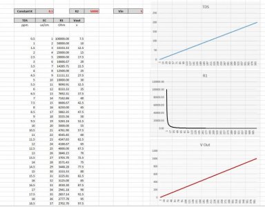
The first thing we need to do is to determine the slope for our circuit since we changed our resistor R16 and R17-R19 group to make it work in the range that we want so let’s assume that our circuit has been modified to measure a range of resistance between 100kohm and 25ohm (as in R17-R19 are 100Kohm and R16 has been adjusted until the Vout of our circuit is just under 10V for a measured R of 25 Ohms)

To do this (one time only) we connect a known resistor (R1) of say 80kohm to the measuring terminals and read the voltage (V1) and repeat this for (R2) of say 50ohm and get (V2) theoretically we don’t need to do this because we have the slope already from the fact that we know that at 100kohm we get 0V and at 25ohm we get 10V but we should do it to correct any changes in output that come from the small differences between R17 R18 R19 in the Wehatstone bridge

Now with R1 V1 and R2 V2 pairs we can determine any unknown R3 by measuring V3 and using the ecuatons from my previous post.

At this point we have an AC ohm meter with a range of 25-100000 ohms and a few tests should be carried out to determine circuit stability and precision. So we can connect a known resistor of say 1kohm and measure the output periodically over a period of say 24hrs (this will give us the repeatability characteristic of our measuring circuit). Then we measure a linear array of resistor values (like you have done in your test for me) to get an array of voltage outputs that we plot in a graph to assess the linearity of the circuit (we should get a straight line)

So we now have a circuit that we know all the characteristic of and are confident that any error in measurement that may occur is not due to circuit errors.

Calibration (it’s essentially the determination of K)

We connect the probe with an unknown K constant to the circuit and we put it in a known conductivity standard. Measuring the voltage V3 and knowing the slope of our output we determine the resistance (more like resistivity) R3. Now that we know R3 and EC of the standard we determine the actual K of the probe.

Measurement
From here it’s easier. We put the probe in an unknown EC1 solution and measure V4. From V4 and the slope we determine R4. From R4 and K we determine EC1.

All the math is done internally in the MCU and this is essentially a 1 point calibration (the first part of determining the output slope of the circuit is only necessary when changing the values of the R16-R19 resistors as this affects the way the MCU does the math. Once those resistors have been established and common values for them are found with low tolerance, the MCU is programmed accordingly and we can duplicate the circuit without worrying about those resistors any more)

In my software you put the probe in a known EC standard and give the calibration command together with the value of the conductivity of the standard the probe is in and that’s it. You can then read the EC of the solution and the actual K of the probe.

After each calibration we can look at what happened to the K constant since last calibration and assess if the probe needs cleaning or reconditioning as if the probe K goes too far from the intended constant that we first used to determine the range of our circuit in the beginning, than we are essentially shifting the measuring range (it will still work. Just not in the range that we need to)

Issues
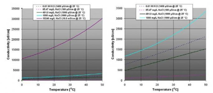
This design as we know has a linear voltage to resistance response as opposed to voltage to EC. There are a number of advantages in using this design for EC measurement from circuit stability to the use of instrumentation amplifiers and temperature compensation. HOWEVER the one disadvantage that I can think of is actually a deal breaker in the use of this system for measuring low EC in the ppm range (I still think you should build it and test) and it has to do with the fact that at as we see form the charts posted before the non-linear relationship between EC and Vout makes it very hard to scale the AD channel of the MCU to measure accurately at low PPM and still keep wide range (if you know what I mean)
It’s great for high EC values in the range of 50ms/cm as the curve is not so accentuated and the loss in AD resolution is negligible. (If you build it and see that it’s no good for low ppm you can always use it as a salinity module)

Temperature compensation
This is not simple. In the industry some of the lower end meters employ a linear compensation of around 2% per centigrade or something of that sort (this is really not very good) as the relationship between the temperature and conductivity is not a linear one and it depends mostly on the effect of temperature on the movement of ions but also the type of ions that move in the solution.
Here is a graph of how temperature affects conductivity.

attachment.php


Now if you look at this you might realise one of the reasons I used this type of circuit. It’s a bit much to explain and im still testing for this but it’s a bit like this:
The effect of temperature on EC values is non-linear with an exponential type curve but if we go back a few steps and remember what we are actually measuring, which is Resistivity of a solution, and we look at the effects of temperature on that, we see that they are inverse exponential (not really but I’m just trying to make it easier to understand) so by measuring applying the temperature compensation to the R values not the EC values we are linearizing the effect of temperature enough to be able to use a simple equation (not sure this makes enough sense)

In other words if we obtain a voltage that is linear to EC and apply temperature compensation to that we need to bend the EC curve. But if we have a voltage that is linear to R and nonlinear to EC it and we apply out compensation to R rather than EC we bend R and straighten EC (this is all very much theory and needs testing so please take it as such)

A method that is proven for temperature compensation is to determine a trend line for the curve in the solution you are measuring and derive an equation form it or create some lookup tables in your MCU or PLC

It would be good if you can build this as you say so I can get some feedback in the use of it as low EC detection (I don’t expect it to do very well in the low ranges)
Let me know if you don’t have any of the components needed and I’ll send you some (I know that INA128 is expensive but I have a few so I can spare you one)

I hope this sheds some light on the subject
Happy building
 

Attachments

  • Capture1.jpg
    Capture1.jpg
    35.3 KB · Views: 8
I'm think i got it :-) at last, many thanks for the explanation .
We connect the probe with an unknown K constant to the circuit and we put it in a known conductivity standard. Measuring the voltage V3 and knowing the slope of our output we determine the resistance (more like resistivity) R3. Now that we know R3 and EC of the standard we determine the actual K of the probe.
Known conductivity standard must have its reference temperature, that is I have to warm or cold this liquid to its reference temp in other way it will do not have a correct declared EC.
In other words if we obtain a voltage that is linear to EC and apply temperature compensation to that we need to bend the EC curve. But if we have a voltage that is linear to R and nonlinear to EC it and we apply out compensation to R rather than EC we bend R and straighten EC (this is all very much theory and needs testing so please take it as such)
That is a great idea, please let me know when You do some test and develop some equations.
From where do You get this charts witch temp in EC functions for different salinity ?
I can think of is actually a deal breaker in the use of this system for measuring low EC in the ppm range (I still think you should build it and test) and it has to do with the fact that at as we see form the charts posted before the non-linear relationship between EC and Vout makes it very hard to scale the AD channel of the MCU to measure accurately at low PPM and still keep wide range (if you know what I mean) .
I think I know what do You mean, it is 1/R so the change of R is not linear to the EC, and in some range that is ~50-300uS the curve is most curved :-D and the measurement will be not accurate, because small change or R make big change of uS. If will want to measure a low PPM I can set max that is 10V not to 25ohm but for example to 25K or even build two meters for 2 ranges.

Let me know if you don’t have any of the components needed and I’ll send you some (I know that INA128 is expensive but I have a few so I can spare you one)
It's very kind of you, what country do You from ? it is possible tha the shipping can cost more than integrated circuit itself :-(


I have one more question, what exactly is the constant K, it has something in common with electrode impedance ?

Author of that circuit I already build write that:

“The component values used in this circuit support a probe having a impedance of about 690ohm, 4EC (aka 2Kpp) Value of R7 can be changed or replaced with a pot to compensate for the probes are to weird. … blab la bla … Probe impedance can be determinate by measuring gain of U1b stage. Measure Vin at pin5, Vout at pin 7 using AC meter.”
Rf= Feedback resistor R8 with is 6800 ohms
Rx = Rf/((Vout/Vin)-1)
So for example Vin=.2v Vout=2V probe impedance = 755 ohms”

I know that it is not You circuit but You knowledge is impressive so maybe You can figure it out to.
I try to measure my probe impedance, I measure the Vin it was 0.04V ant Vout was to 0.04V I measure it to the ground of circuit. So I think It should be measured when probe electrodes are have a short circuit. I measure it again and Vin = 0.04V , Vout = 8V. So my probe impedance is 35ohms ?
That is very low impedance.. author says that this circuit is set for 755 ohm, should I change the R7 to 120K or add some extra resistors on the probe electrodes ?
 
hmm...
i don't think you should concern yourself with impedance for this application presonally so im not going to go ito that. (plus im not sure i understand the implications much better than you)

constant K is a value that describes the relationship between the electrode plates and the distance between them. the formuala is simple. its the area of the electrode plate devided by the distance between the plates
a probe of K=1 is made of two plates of 1cm square placed 1cm appart

im in englad. i assume you are in poland? if so i dont think its too big of a deal to post. It might be worth it if you need the pcb op amp and maybe a preprogrammed microcontroller. that way you can connect it to a pc via a serial cable and play with some tests before you implement into your PLC. (just a thought)

one last thought
keep in mind that this type of analogue approach to measuring tds is not really the best way to go and when Ill finish de development of my tds module im sure you'll be impressed with the performance and you will want to build that as well.
i think i mensioned this before but im aiming to get an accuracy of arround 0.1 tds (fingers crossed)

best of luck
 
0.1 TDS that is impressive :-) I'll cheer for you.

Ok, so please check the cost of shipping and let me know.

I have a private question, You said before that English is not Your first language, and there is a name Bogdan in Polish, and that is first part of Your nick :-) so maybe You are came to England from Poland ? If it's to private just ignore that question. Sometimes I tend too nosy, I apologize in advance.
 
just realised that i didnt answer all your questions....

i find temperature compensation for conductivity to be one of the more confusing compensations that i worked with. im saying that to draw your attention to it and avoid pitfalls that i fell in while working on this.
In my post i was describing the functionality of my sistem and that takes into account temperature so any value that i called EC is actually standardised EC @25deg (if that makes sense)

The chart came from a study made by some people i found in my development process i spoke to them and they tought me alot and i trust their measurements. (but that just me)
 
porlock,
I have a question for you as well if you dont mind
what made you chose the PLC you have?
have you considered using and arduino or a raspberry pi before settling on the PLC?
 
There is a couple of things that is why i decide to use Wago PLC
1) When I start to build my aquarium setup hmm more or less 8 years ago, then I decide what to pick. Arduino was not so popular, to be honest I do not heard about it then.
2) Then (that is 8 years ago), I use a PLC controllers at work, so I already have the knowledge and support.
3) Wago is commercial automation solution so it is very stable, and well designed.
4) Wago have a module construction, so i can add any module that I want (Modbus, RS232, RS234, ect.)
5) I plane to use it to intelligent house Wago have a proper modules to some inteligent house protocols (but I do not have time, maybe in future)
6) My controller have a build in web server, and natively supports Ethernet protocol.

I constantly develop something new to my setup, automatic water change, flood alarm, SMS and email alarms, central heating, HCL and Co2 control, water level in sump, etc.

And I can tell you my biggest secret ;-) I do not have a reef tank I have a 500l fresh water discus tank :-)
I register on reef central forum just for this thread :-), but like You see a common goal can join fresh and marine water aquarists :-)
 
hmm
this discussion might deviate from the subject of tds and maybe we should move it to a more appropriate post or PM.
i have designed a few sistems for discus tanks in particular
a very compact automatic frozen beefheart mix feeder
and a high capacity algae scrubber (you can go for up to 6 months with no water change (i wouldnt really but its possible))

the sistem i'm designing uses a raspberry pi with the root files system on a 64gb ssd which makes it very stable and glitch free. in this sistem there are a total of 37 different modules for measurement, control and connectivity from the basic stuff like temp, ph and tds to more complex like automatic alcalinity titration, optical DO and CO2 sensors and true automatic water mixing station/top up. for true reliability i added a gsm module to be able to actually call the sistem and get updates and perform tasks in case of no internet in your home .
if you like we can talk more in private about all of this so as to not flood this post wiith matters not relating to EC and TDS

and back to TDS i had a thought and i would like to make a suggestion
i advise that you combine our two circuits to get the best of both worlds
1) use the ac sine generator from my schematic (i found it to be much more stable)
2) use the op amp stages from yours
3) use the signal rectification from mine (less components. no bridge rectiffier and you have a spare op amp module from the signal generation part)
4) try and get rid of all the trimmers and do software calibration as we discussed in previous posts (you shouldn't have to take a screwdriver to your circuit everytime you need to calibrate)

hope my input has been usefull for you and anyone else interested in this subject
good luck
I will PM you to get address for postage
 
hmm
this discussion might deviate from the subject of tds and maybe we should move it to a more appropriate post or PM.
i have designed a few sistems for discus tanks in particular
a very compact automatic frozen beefheart mix feeder
and a high capacity algae scrubber (you can go for up to 6 months with no water change (i wouldnt really but its possible))
Sounds cool :-) specially that frozen beefheart mix feeder, and automatic algae scrubber, and how do You achieve that 6 month no water change.. , please write to me on PW :-) I'm very curious how this work. At evening I will send You decryption of my solution that I use central apartment heating to heat my tank and automatic HCL dispenser to PH control. This is not every sophisticated solutions but they work fine.

i advise that you combine our two circuits to get the best of both worlds
1) use the ac sine generator from my schematic (i found it to be much more stable)
2) use the op amp stages from yours
3) use the signal rectification from mine (less components. no bridge rectiffier and you have a spare op amp module from the signal generation part)
4) try and get rid of all the trimmers and do software calibration as we discussed in previous posts (you shouldn't have to take a screwdriver to your circuit everytime you need to calibrate)
The main problem of my current circuit is that the low uS correspond to the very low mV, and there is a variation of +-15mV in the circuit. Even if I touch the wires, on turn on the desk lamp it can affect the measurement, mV is not good for reading the output, It should be higher, to achieve that I make some adjustment in R7 in the Current to Voltage amp stage. I change it to the 30K, and that I was able to get 200mV to 10uS. But the curve become more flat and the measurement more that 200uS have a big error factor, look at the attachment.
So my idea is not good.. I spouse R7 must stay at 6.8K, do You have any idea howto move the curve to higher voltage and not afect the curve it self ?

I think If I want to get S=1/R on output I can't change signal rectification stage to that one from Your project, because I think that in this stage this calculation 1/R Is made, I can be wrong :-) but something tells me that is in this section by U1C amp. What do You think ?
 

Attachments

I was wrong, there is no 1/R calculation at all.. i measure a VAC output of current to voltage amp and this output was curved, but in opamp itself Vout is linear to current, so there can be only one proposal, R of the test liquid is not linear to the EC, am I right ?
 
Last edited:
Back
Top