DIY LEDs - The write-up

Status
Not open for further replies.
You should do a build like widmers. You can mount the LEDs on the ceiling with great results.

Nice to know the projector concept is still being recommended. It is downright stunning for a rimless tank, but I must say I give credit of the concept to LiveForPhysics. Here's a sneak peak @ the newer version I'm in the middle of building...

107.jpg


109.jpg


3 ELN-60-48s, 12 cool XPG, 12 neutral XPG, 24 royal XPE, 12 degree lenses.
Notice the cream of mushroom soup for scale; everything is getting packaged into a 3 foot by 3 inch by 4 inch housing...
 
Good to see you Widdy. Fascinating.

I hope you're taking lots of pics for a stand alone build thread! (or we'll hunt you down and inject you with one of your lab assignments)

You paralleling the RBs?

Why is that cross piece mounted on the top? Why not down in between the tubes so everything fits into the unit volume? Aesthetics...
 
Very nice!

Where'd you get the aluminum?

I found some 8020 on eBay that looks good, although it's almost retail price anyway. Maybe I could order it and get it anodized black.

I found some C channel with flanges (like a "G" channel") that would be PERFECT to slide a 1.8" plexi shield into ... all in one basically. But the minimum was 300 pounds :)

== John ==​
 
@k LOL I actually haven't been taking too many pictures... It just goes together so fast and these ELN-based builds are a dime a dozen now. But I will have a build thread for it just so I can reference it to keep things organized when I do the aquarium build thread (along with referencing separate threads for the cabinet build, tabletop display ATS, etc...)

And yea the RBs will be paralleled. I originally was going to use two of the ELNs to drive the 24 RBs, but A) I was running low on space, B) I would probably have them tuned to 700 mA either way, and C) harmonics in a 100+ yr old house... But that's OK, I also have 24 extra RBs that I can combine with my 4th ELN to make a nice plant light...

Speaking of AESTHETICS, couldn't agree with you more. I'm come to a place in this hobby where aesthetics is one of my primary concerns. That cross peice does appear to be hideous right now, but rest assured, everything will be packaged into a sleek 4" by 3" (cross section) enclosure.

@j I stumbled across a metals supplier here in Ann Arbor which is like DIY paradise with every size and shape of these materials imaginable. The 2"x1"x36" aluminum tubes cost around $10 ea. But I did see them for a similar price on amazon of you don't have anyone local.
 
Last edited:
If you were going to lose the halide I would suggest 48 over the tank...therefore you don't need 24 on each side of the halide. I think 12 on each side would be good but you may find the sides are brighter than the halide. Think about mixing 2RB to 1 White...you said you wanted more blue. and make sure you go dimmable kits so you can mix color and dim to your liking and to match the halide. Since you're about 10 inches from the water get the widest optic they have with the kits....I think they have 80 degree lenses.

Thanks for responding on this. I have a new bulb, which is why i am not ready to lose the halide yet.

So it would work out to be: 12 total: 8 Blue and 4 White on each side?
I am not sure if it is more blue or more white i am after. I know that i need more light on the sides, as you can see in the pictures. I want to go dimable so i can control them with the Neptune Apex.

Being 2 feet deep and the bulbs might be closer to the water to keep the height of the housings the same. If i was 6 inches from the water would you still recommend 80 lenses? Thanks!
 
Sorry for the double post but cannot edit my previous one. After doing some more reading I ended up deciding how many leds I need and drivers, although I am still debating on which HLG driver to use. It will either be 2x HLG-185-42B + 1x ELN-60-48D or 2x HLG-185-48B + 1x ELN-60-48D. As it follows:


1x HLG-185H-42B (4.4A)
36x Whites XP-G
4 Strings - 9 CW / 9x NW / 9x CW / 9x NW
Running at 1100 mA per string /will probably be dimmed to 900-1000mA/

1x HLG-185H-42B (4.4A)
50x Royal Blues XP-E
5x Strings - 10x RB each string
Running at 880 mA per string /will probably be dimmed to 800 mA/

1x ELN-60-48D
Series - 8x Blue, 2x Royal Blue, 2x Red
at 800 mA

OR the other route is:

1x HLG-185H-48B (3.9A)
36x Whites XP-G
3 Strings - 12x CW / 12x NW / 6x CW 6x NW
Running at 1300 mA per string /will probably be dimmed to 900-1000mA/

1x HLG-185H-48B (3.9A)
48x Royal Blues XP-E
4x Strings - 12x RB each string
Running at 975 Ma per string /will probably be dimmed to 800 mA/

1x ELN-60-48D
Series - 8x Blue, 4x Royal Blue, 2x Red
at 800 mA

I just don't know which is the better route and what are the benefits /or disadvantages/ of using:
42B model - more stings, less leds in a string
48B model - less strings, more leds in a string
Indeed using 42B model is giving lower overall current per string but it will be lowered by dimming the leds anyways.

Am I missing something?
The only thing I could think of is that if I ever want to run the leds at higher output, the 48B driver would be a better choice by giving me 1300mA for whites /XP-Gs max is 1.5A/ and 975mA for blues /XP-E max is 1A/, however with that many leds for my 120g tank I don't think I'd push them that far near their maximums.
 
Last edited:
BTW where'd he get off to? [kcress]
VACATION !!!!
VeL, I don't think it it matters. I would probably go higher voltage, but only because I think fewer strings are easier to work with.

Before I left I did a comparison of the XM-Ls and XP-G efficiency and and was surprised that they were the same. Some one pointed out that I used different current. I used XP-Gs (350ma) and XM-Ls (at 700ma), because reading the datasheets I took these as the Cree recommended current (I know they can go higher and lower) and these are IMHO. But in order to get a fairer comparison what do folks think the currents should be?

I think I pointed that out. I think you do something along these lines: take the lumen output of however many xpgs you are using at a given current. Compare that to the lumen output of the same number of XML at the same current. Or find out the number of XML needed to to supply the same number of lumens. Also, keep in mind the the watts consumed by a XML at the same current as the xpg is less.

While the lumen output of the xml may be the same/ higher/ lower than the xpg, the XML use less energy to do the same amount of work.
 
For those that don't recall the discussion:
XM-L T5 are 260 at 700 ma and 2.9 volts or 128 lumens / watt
XP-G are 139 at 350 ma and 3 volts or 132 lumens / watt


Compare that to the lumen output of the same number of XML at the same current.
I disagree because XMLs are designed to run hotter so IMHO the same current is out. So it make sense the XMLs should have more current (so fewer LEDs for the same output).

Or find out the number of XML needed to to supply the same number of lumens.
but at what current? I picked (I think) the manufacturers recommendation.

Also, keep in mind the the watts consumed by a XML at the same current as the xpg is less
A watt is a watt. XML require less current to reach a voltage (so consume less power/watts) it really boils down to how much light/lumens/PAR/PUR is produced.

While the lumen output of the xml may be the same/ higher/ lower than the xpg, the XML use less energy to do the same amount of work.
That is why I was comparing lumens per watt.

The question is where are most people operating these. If someone calculates I need to run my XPGs at 350 ma to get X lighting then thinks I will save money by buying 1/2 as many XML and doubling the current to double the light. Then they would be wrong. Now it maybe true at 700 and 1400 (I would have to do the math), and probably many other values. I think we need to find out where most people are running the XM-Ls.
 
From my reading I would guess most people are running XP-Gs around 700ma. So:
139 lumens * 187% / (.700ma * 3.2 volts) = 116 lumens / watt
for a XM-L
2 LEDs * 139 lumens * 187% / 260 lumens = 200% so at 200% the XML current is (I would guess from the chart) 1550 ma and at that current the voltage is 3.1 so
2 * 139 & 187% / (1.55 * 3.1) = 108 lumens per watt
So it appears the trying to save electricity by using 1/2 as many XM-Ls is not going to work. However you can save electricity by using the same number of XM-Ls as XP-Gs (having them produce the same amount of light). Or some other ratio of XP-G to XM-L less than 2 to 1. I guess that might be some math for tomorrow :)
 
Okay, I see what you mean now.

I agree, at the same current, XML are more efficient than xpg. Because the increase in lumens isn't linear, the lumen output doesn't increase at the same rate as the current. So would technically need closer to 5/8 the number of XML ruining at twice the current as you would have had with the xpg for the same amount of light.

I've argued two points before, based on what you just pointed out. Use around half the number of XML at just over double the current for lower upfront cost with a bit higher energy cost long term (because xpg are around $4.50 while XML are $6.80 or so) or use the same number of XML as xpg with the same current for higher upfront cost but savings long term in energy consumption.

I haven't done the math, but I would put my money on the first option being cheaper long term. 20% energy savings isn't a whole lot per year on a 300 watt fixture. I think the extra cost of all those extra XML could be more at this point.

Im just guessing.
 
Is there something I can put across the dimming circuit on an HLG to keep it from going open as a failsafe in case the control creates an open circuit? Trying to prevent the driver from driving at full power if that happens. I would prefer something that would result in approx. 10K ohms of resistance across the circuit if the controller goes open. I'll be dimming using 1v-10v from an Apex.
 
No I went the other direction to the Blue Ridge Mountains. As near as I can tell no power loss from the earth quake or hurricane :).

jkopp36,
What current do you need to limit the HLG to? I mentioned it somewhere (kcress do you remember?) about adding a parallel resistor to a 100k pot that will keep the voltage down.
 
jkopp36,
What current do you need to limit the HLG to? I mentioned it somewhere (kcress do you remember?) about adding a parallel resistor to a 100k pot that will keep the voltage down.

I've got the voltage capped by using a resistor and diode so that it does not go over a certain amount but I'm worried about the possibility of an open circuit which would cause the driver to run at full throttle+ and thought that if I could just put a 10K resistor accross the circuit right at the driver it would be a good failsafe. I'm guessing it's not that simple but that there might be a way using some other components along with it. I'm not even sure what happens to the variable voltage ports on an Apex if it loses power or something so it may not even be that big of a deal but I like redundancy whenever possible. Hopefully that makes sense.
 
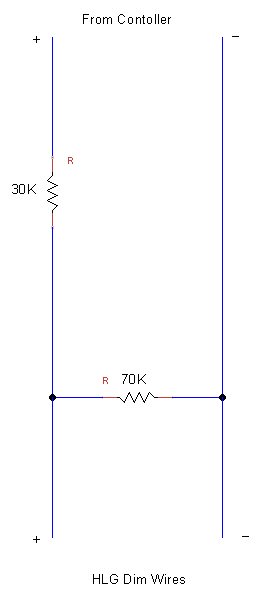
Making up some numbers then. Lets say you need to limit the current to 70% of the HLG output. There are three ways to control the current:
- PWM - not applicable but even in this mode you can't go above 70% for the voltage. Anyone know if they really limit the current or pulse the current? Reading the datasheet it look like it limits the current.
- Resistor only you would need a 70k ohm resistor across the the dimming signals
- Voltage would need to be limited across the dimming signals to 7 volts.

So if you removed your controller you would want a 70k ohm across the dimming signals. So start there. Now the controller can output 10 volts and you need to limit it to 7 volts. Using a resistor you can add a 30k and you can never reach more than 7 volts.

+- Up to 10 volts from the controller
|
30k resistor
|
+ Dimming + to the HLG
|
70k resistor
|
+ Dimming - to the HLG and ground reference of the controller

Your only risk is that the 70k resistor comes loose and I don't see a way to mitigate that risk. I assume you still plan for fuses in your circuits.
 
Sure show off for the crowd with fancy pictures :)

But, yes that is what I mean. It will also allow for the full range of the controller's dimming. Just change the resistors for whatever percentage you need.
 
Sure show off for the crowd with fancy pictures :)

But, yes that is what I mean. It will also allow for the full range of the controller's dimming. Just change the resistors for whatever percentage you need.

lol - sorry, I've just burned up enough stuff in my time that I wanted to be sure.

Can I just use common resistors available at RS?

Thanks for the info. Good stuff!
 
Status
Not open for further replies.
Back
Top