oreo57
Well-known member
There's no problem with the WB of my photo? Must be your eyes...... You need to get them checked.:lol2:
well maybe I just like this green one..
")

There's no problem with the WB of my photo? Must be your eyes...... You need to get them checked.:lol2:
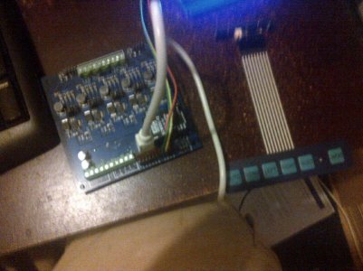
LOL- I think I have about 6 hours of time invested in those. 2 hours here, 2 hours there, it starts to add up quickly. Built another 10 last night, just for the sake of having some ready for the next request.
so it finally happened.. US labor cheaper than in Mumbai...
:uhoh2:
Hey O2,... do you recall my pcb's,... they were to be used for 1400ma output, and I changed some rsense resistors to get a few 700ma boards. Can I make another resistor change for a 3A output channel on one of the boards? Thanks,---Rick
O2 i cant send pm
didn't know he had to change out all the different parts glad I am at 1.4 and staying.. he could always cool it down with a cold beer")

I consider the 3 amp rating of the chip a bit misleading. Sure- it can do 3 amps if you're only driving an led with a Vf of 12V or less from a 48V supply. It'll run hot but it's not impossible. Try the same scenario with a 36V led and the chip will run over 200 C in no time flat. I suppose if you like warm beer it's doable.
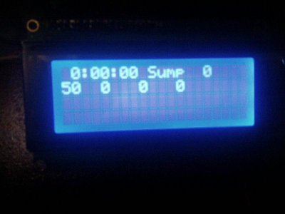
Thermal Budgeting
The A6211 is capable of supplying a 3 A current through its
high-side switch. However, depending on the duty cycle, the
conduction loss in the high-side switch may cause the package to
overheat. Therefore care must be taken to ensure the total power
loss of package is within budget. For example, if the maximum
temperature rise allowed is ΔT = 50 K at the device case surface,
then the maximum power dissipation of the IC is 1.4 W. Assuming
the maximum RDS(on) = 0.4 Ω and a duty cycle of 85%, then
the maximum LED current is limited to 2 A approximately. At a
lower duty cycle, the LED current can be higher.


I'll leave the translation into human speek to you.........
For discussion...
http://www.digikey.com/rdl/4294959899/4294959833/952
cute Evaluation board..$103.. how much in SOCAL Mumbai???
I suppose I should at least ask a question..
does this imply you can "easily" run it at 3A "IF" you limit it to say 50% duty cycle???
Does a high current yet "dimmed" output offer any advantages??
Besides the disadvantage of someone wanting it to go to "11"...
Sorry just "thinking'...
I can't imagine what other led could fit that particular voltage/current scenario.
Nope. An LED driven at 1.5A 100% PWM will output more light than the same LED driven at 3A 50% PWM. And the one run at 3A will be putting out more heat (never mind the extra heat from the driver)...Does a high current yet "dimmed" output offer any advantages??