Hey O2,...Threads been quiet for a while now, any updates? :bounce3:
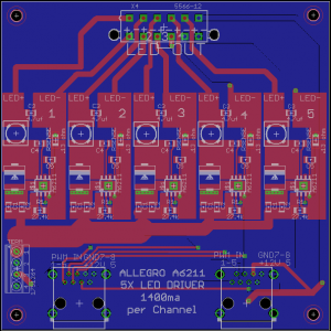
Unfortunately my job has been keeping me quite busy as of late, and it's been 100 degrees + at my home for the last few weeks. I'm relegated to doing my experiments out in the NON Air conditioned garage, so at these temperatures, my motivation wanes quickly. I'm working on a few different versions of the A6211 driver PcB and still attempting to find a way to adequately cool my little LDD-H replacement driver, as time permits. I'm going to order another batch of PcB's that will include a 14mm x 12mm solder pad on the underside of the PcB. The solder pad will allow me to attach a heat sink directly to the thermal tab of the A6211. Hopefully this modification will provide the additional cooling that's needed. Here's a photo (the blue square is the heat sink mounting tab)