Meanwell LDD driver: for those who want to dim to 0 using Arduino

O2Surplus;22396037]Thanks for the head up, because this thread is the last place on the internet that I'd expect to find a Pcb designed expressly for mounting MeanWell LDD's. I'm betting your computer's government controlled search engine had a hard time finding this site.

Sorry my english, I am from Portugal. I don´t understand what you said..Did I said something wrong
I know you build the pcb and I have to congrat you, I know they copied your work but I just search and find it sorry for that.
 
Last edited:
Sorry my english, I am from Portugal. I don´t undersand what you said..Did I said something wrong
I know you build the pcb and I have to congrat you, I know they copied your work but I just search and find it sorry for that.

Please forgive my ignorance. I didn't know you are from Portugal. Being that you are new to this Forum and only have 3 posts, you appeared to be a possible "shill"for the company,who's product you posted a link to.

This forum gets posts, similar to yours, that end up being from persons affiliated with non sponsor company's that pose as product reviewers. They are trying to sell a product and use online forums to advertise their wares. It's a very dishonest practice, so people tend to react negatively when they see such posts.


No, I am not that kind of person. Congratulations again for your work.
http://www.recife.pt/viewtopic.php?t=959
I will need your help to connect the leds to arduino, and I will buy the real ones MW.
help me, the drawing is correct?
16566343_FphIS.jpeg
 
LOL, it looks more like Rrasco's than anything else. It's 130mm X 80mm. I'm sure more companies will jump on the band wagon with the same idea. It's too bad for them that the designs on this forum have progressed to the point that the Pcb's can no longer be assembled by machine. The mix of SMD and through hole components makes soldering by hand the only option for mass production. Not that China's lacking enough labor to do so- LOL.

.....so you know they do make SMD LDD's now as well as SMD terminals and SMD pin headers if you still want removable LDDs............. Doh! I just tipped of the mass producers in China! :lolspin:

Speaking of, I now see that cutter electronics and that one place that I can't mention, along with Coralux now sells the boards originally designed here.................or variations there of. They are popping up all over the internet now after a year.
 
On the positive side, maybe someone will come up with some sort of twist not thought of yet. I remember long ago the simple pull down resistor add on. :lmao:
 
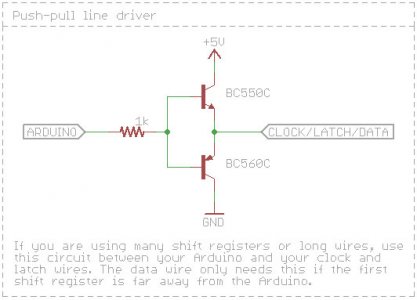
I'm going to keep reading (on page 25 so far).. but has anyone had long PWM signal runs that needed small transistor circuits to boost the signal? I forsee this being needed for the way I have my controller and stuff setup. I found the following little circuit online.

push_pull_line_driver.jpg

Thinking it'd be awesome if I had someone draw up a small board with a dozen or so of these little circuits on them! ;)

Also - it should help in running drivers in parallel via one PWM pin from an arduino. So far I've read your max amp rating on a single PWM pin is 30mA. How much do the different drivers (L or H) pull?
 
LDD pull in the microamp range, so you won't be maxing out a single Arduino pin until like 750x LDD.

Very nice. What about signal wire length? Anyone find a little transistor circuit like this is needed when the PWM signal wire is too long and signal is degraded?

I'm guessing mine will be over 15 ft based on my setup.
 
Hey O2,....morning. I have a question,...you have used Digikey for parts,...my original 6211 ship date is 3/12, when I check the order status it shows original lead time, now current lead time 3/19. Does that mean they have backed up my ship date, or is the 3/19 date for orders placed right now? Thanks,---Rick
 
Hey O2,....morning. I have a question,...you have used Digikey for parts,...my original 6211 ship date is 3/12, when I check the order status it shows original lead time, now current lead time 3/19. Does that mean they have backed up my ship date, or is the 3/19 date for orders placed right now? Thanks,---Rick

Rick-

I suspect that the new date is the lead time for everyone. My order was originally scheduled to ship yesterday LOL, but now it shows the same date as yours. I think we're both screwed for the time being.
I perform a search for the chip at least once a day, just to see if it may have popped up anywhere. Find chips & Octopart always show it being out of stock at all the major distributors. Octopart showed a seller on Amazon as having them available, but when you check the Amazon listing, the chip is out of stock. The funny thing is- Amazon's own "pop-up"advertisements show availability from other more obscure sources, some of which are component resellers right here in the USA. I've sent RFQ's to a few of them, but they haven't responded. My guess is that they won't bother with small orders of just 100 chips or so. I'm going to keep trying though, and I'll let you know if I make any headway.
 
I've been away from this thread for a while because I decided to go another direction with my lighting, but now I'm thinking I can use the 48V meanwell knockoff PS I got and the 4 100,a LDD drivers that are mounted to one of rrasco original 4 up boards to run these Chinese LED's I got.

My questions are...

1) The LDD PWM is 0-5v not 0-10 that my Reef Angel uses, is that correct?
2) The RA has dim+ and dim-for the PWM channels. Where can I ground the PWM channels to?
3) Will these dim to 0 without the pull down resistor?
4) If I want to add the pull down resistor it goes from the PWM pin to ground correct? Do I just scrape the back for a grounding place or is there someplace already open I can use?
 
I've been away from this thread for a while because I decided to go another direction with my lighting, but now I'm thinking I can use the 48V meanwell knockoff PS I got and the 4 100,a LDD drivers that are mounted to one of rrasco original 4 up boards to run these Chinese LED's I got.

My questions are...

1) The LDD PWM is 0-5v not 0-10 that my Reef Angel uses, is that correct?
Yes- But your reef angel should be able to produce the needed 5V pWM signal since it's an Arduino based controller
2) The RA has dim+ and dim-for the PWM channels. Where can I ground the PWM channels to? Connect the dim- wires to ground on your LDD-H PcB.


3) Will these dim to 0 without the pull down resistor? Yes

4) If I want to add the pull down resistor it goes from the PWM pin to ground correct? Yes
Do I just scrape the back for a grounding place or is there someplace already open I can use? That's what I did using SMD 1206 resistors, or solder a conventional "through hole" type resistor between the PWM & VIN- mounting pins of your PcB.
 
Thanks O2.

The RA is capable of the 5V pWM signal. The latest version of the dimming module has jumpers inside so I can choose between analog or PWM and 0-10 or 0-5v for each of the 6 channels. It gives me a wide range of options.

What value resistor is needed again (IE Ohm and v). I know it's in this thread but 98 pages and 2433 posts is a little hard to look thru.
 
Very nice. What about signal wire length? Anyone find a little transistor circuit like this is needed when the PWM signal wire is too long and signal is degraded?

I'm guessing mine will be over 15 ft based on my setup.

15' is no problem, if you were talking hundreds of feet maybe. I'm running just under that distance from a StormX which is limited to 10mA on the PWM signals, no problems what so ever, standard arduino can output 40mA. So you should be just fine.
 
Ok this is the board I have...
LDD012_zps86353e8d.jpg


Can I scrape anywhere to get to the ground?
Also I'm not really following on where I need to connect the pull down resistor for each of the channels.
 
Ok this is the board I have...
LDD012_zps86353e8d.jpg


Can I scrape anywhere to get to the ground?
Also I'm not really following on where I need to connect the pull down resistor for each of the channels.

You can avoid scraping if you use conventional "through hole" resistors instead of the tiny surface mount variety. If you're planning to install chip holders for the LDD's, just solder one end of the resistor to the PWM pin and the other end to the -In pin at each LDD. The resistors should be soldered in to the bottom side of the PcB after the chip holders are soldered to the top.
 
My chips are already soldered to the board. Someone started this project and I bought the chips and board from him when he abandonded it. I was going to solder the resistors to the bottom like you said. Where can I solder the ground for the dimming controller to.
 
Back
Top